


No
Item
Description
6
System identification
connector
Connects the optional system status indicator assembly through the
optional cable management arm.
7
System Identification
Button
The identification buttons on the front and back panels can be used
to locate a particular system within a rack. When one of these
buttons is pressed, the LCD panel on the front and the system
status indicator on the back blink until one of the buttons are
pressed again.
Press to toggle the system ID on and off. If the system stops
responding during POST, press and hold the system ID button for
more than five seconds to enter BIOS progress mode.
To reset iDRAC (if not disabled in F2 iDRAC setup) press and hold
for more than 15 seconds.
8
Power Supply (PSU1)
AC 350W
9
Power Supply (PSU2)
AC 350W
For more information, see the Back Panel Features and Indicators section in the Dell Owner’s
Manual.
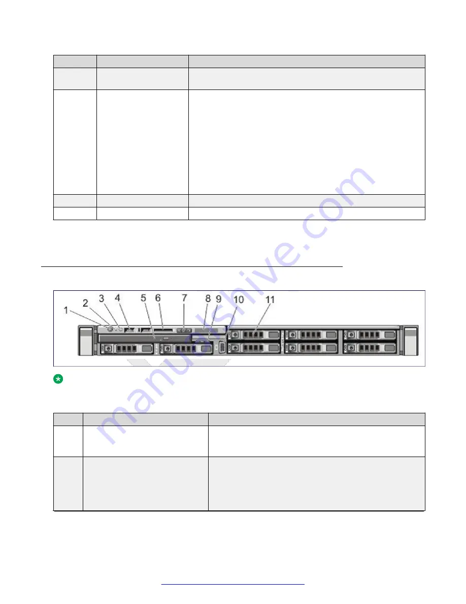
Front view of Dell R620 Server
Note:
The server is shipped with two hard disk drives. The remaining hard drive bays will not be
operable.
No.
Item
Description
1
Power-On Indicator, Power Button
The power-on indicator lights when the system power is on.
The power button controls the power supply output to the
system.
2
NMI Button
The button to troubleshoot software and device driver errors
when running certain operating systems. This button can be
pressed using the end of a paper clip.
Use this button only if directed to do so by qualified support
personnel or by the operating system documentation.
Table continues…
Hardware overview
20
Deploying Avaya SBCE
August 2015