Page 8
IronHorse GSDA-DP-S User Manual – 1st Edition – 09/18/2019
GSDA-DP-S o
PerAtion
The GSDA-DP-S Signal Conditioner is a panel-mounted multiple function device used to either
attenuate (scale or reduce), convert, or generate control signals typically used in laboratory/R&D or
plant/industrial applications. The input signals are analog in nature and specifically in the 0-10 VDC or
4-20 mA range. The output signal can be either 4-20mA or from 0.1 VDC to the Vset voltage (5-20 VDC).
v
isUal
r
eference
GEN
SCL
SPL
ENTER
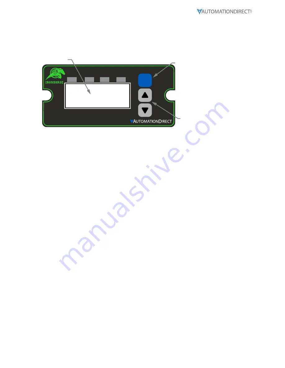
SIGNAL SCALER
AND GENERATOR
ENTER (Select) Button
Up & Down Buttons
Display Window
The Up/Down buttons are used to Scale or Set the output level, in percent (default). The Minimum
Scaling/Generator output is 0.0%. The Maximum Scaling/Generator output is 100.0%. On power up,
the factory default setting is “Last Value”.
When lit, the annunciator LED’s across the top of the GSDA-DP-S indicate the following:
•
SCL:
Scaling mode is active and device output will be either voltage or current, depending on the
jumper configuration� In current output mode the display setting and the input current or voltage
determine the 4-20mA output level� In voltage output mode the display setting, the maximum level
set by the potentiometer R9 adjustment and the input current or voltage determine the output
voltage level; see “Device Configuration” for proper hardware and software setup�
•
Gen:
Generate mode is active and device output will be either voltage or current, depending on
the jumper configuration� In current output mode only the display setting effects the 4-20mA
current output level� In voltage output mode, the display setting and the maximum level set by the
potentiometer R9 adjustment determine the voltage output level; see “Device Configuration” for
proper hardware and software setup�
•
SPL:
The GSDA-DP-S is in Set Point Lock; this effectively disables any changes until IN1/IN2 input
levels change according to the functional configurations� Various modes are available with SPL, please
see parameters 30, 31, 35 and 36, which can be used to configure Set Point Lock�
h
Ow
tO
c
hanGe
a
P
araMeter
’
s
v
alUe
1) Hold down the Enter button until Parameter Mode is entered (parameter ‘P 0’ Displayed)
2) Using the Up and Down buttons, select the desired parameter number to view or edit
3) Press the Enter button to change the value of the parameter
4) Using the Up and Down buttons, change the parameter’s value as desired
5) Press the Enter button to permanently save the changes (Return to Parameter-Selection Mode)
6) Select parameter zero and press the Enter button to return to Running Mode
O
PeratinG
the
U
ser
i
nterface
The LED display has three basic operating modes: Run Mode, Parameter Mode, and Value Mode. Each
of the three modes have specific visual indicators that allow the user to immediately determine the
current state or mode of the user interface. Parameter Mode and Value Mode can only be entered if
the Program Enable jumper is in the ‘P/EN’ position.
Run mode
is the default display of the unit when power is applied. The display shows the target value
in the appropriate user-defined format. The Up and Down buttons increase or decrease the displayed
target value until either the display minimum or display maximum limit is reached.


