


pg
4
Solace / Titan Elite Remote Starter
Installation Steps
Programming and Testing
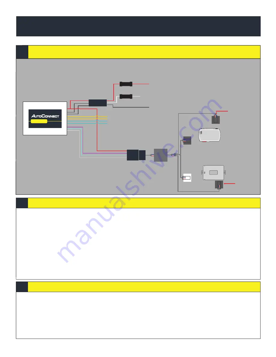
INSTALLATION TYPE 2
AC202
1. Ensure you have swapped the blue and white wire on connector
2. Complete installation of Remote Starter (R.S.) including programming the bypass module in the appropriate
DATA protocol *For Fortin modules you must switch the protocol using the Flashlink Manager. Turn option
F2 AP/OFA to “ON”. If you do not have a Flashlink Manager you must hardwire all connections between the bypass
module and R.S.
3. Program R.S. for M2-11-1(iDatalink 2-way) for Fortin and iDatalink modules.
4. Connect the 2 RF Conn 1, one to the Bypass Module and the other one to the IC4. You will need the extension
cable “Starter Connection Cable” available from CTS Tracking.
5. Mount the Autoconnect module as described in the Autoconnect Install guide Step 3.
6. For true voltage cut and hardwire the Red, Black, and White directly from the Autoconnect device to the
vehicle.*DO NOT CUT THE DATALINK CABLE
1. Open the Autoconnect App or Dashboard
2. Log in to the Autoconnect device installed using the SID # as both username and password.
3. Go to the command tab on the bottom of the app, or the remote function of dashboard
4. Scroll to the bottom of the commands and send the required Installer Protocol.
5. For iDatalink and Fortin Modules select “Set Telematic Protocol”. This option is by default
6. Test all the application functions (Start, Stop, Lock, Unlock, Auxiliaries, ETC. GPS).
7. We recommend affixing the SID Sticker to the door jamb of the vehicle.
AC202
White - Key Ignition Source (+)
Red 12V +
Black Ground
Swap Blue with
white at
the connector
Fuse
Fuse
Bypass Module:
iDatalink
Fortin
*Use iDatalink 2-Way Protocol
RF CONN 1
RF CONN 2
RF CONN 3
IC4
Yellow/Black: Input 1 (Optional (-), Can be used for hardwired alarm)
Yellow/Brown: Input 2 (Optional (-))
Blue/Green: Output 1 (Optional (-))
Green: Output 2 (Starterkill (-))
External Connector: Not used
Swap Blue with
white at
the connector
Starter
Connection
Cable


