background image

Page 7

579-1165AC  Rev C

4007ES Operator’s Manual

4.2.1 Processing Alarms

There are three actions that may be taken when an alarm condition occurs:

1.

 Acknowledge an Alarm

2.

 Silence the Alarm

3.

 Reset the System

Each step is explained in detail in the rest of this section.

4.2.2 Acknowledge an Alarm

Two types of acknowledging modes can be configured on the panel:

Global Acknowledge

All the zones inside the Zone Alarm list are acknowledged at once.

Individual Acknowledge

Each zone inside the Zone Alarm list is acknowledged separately

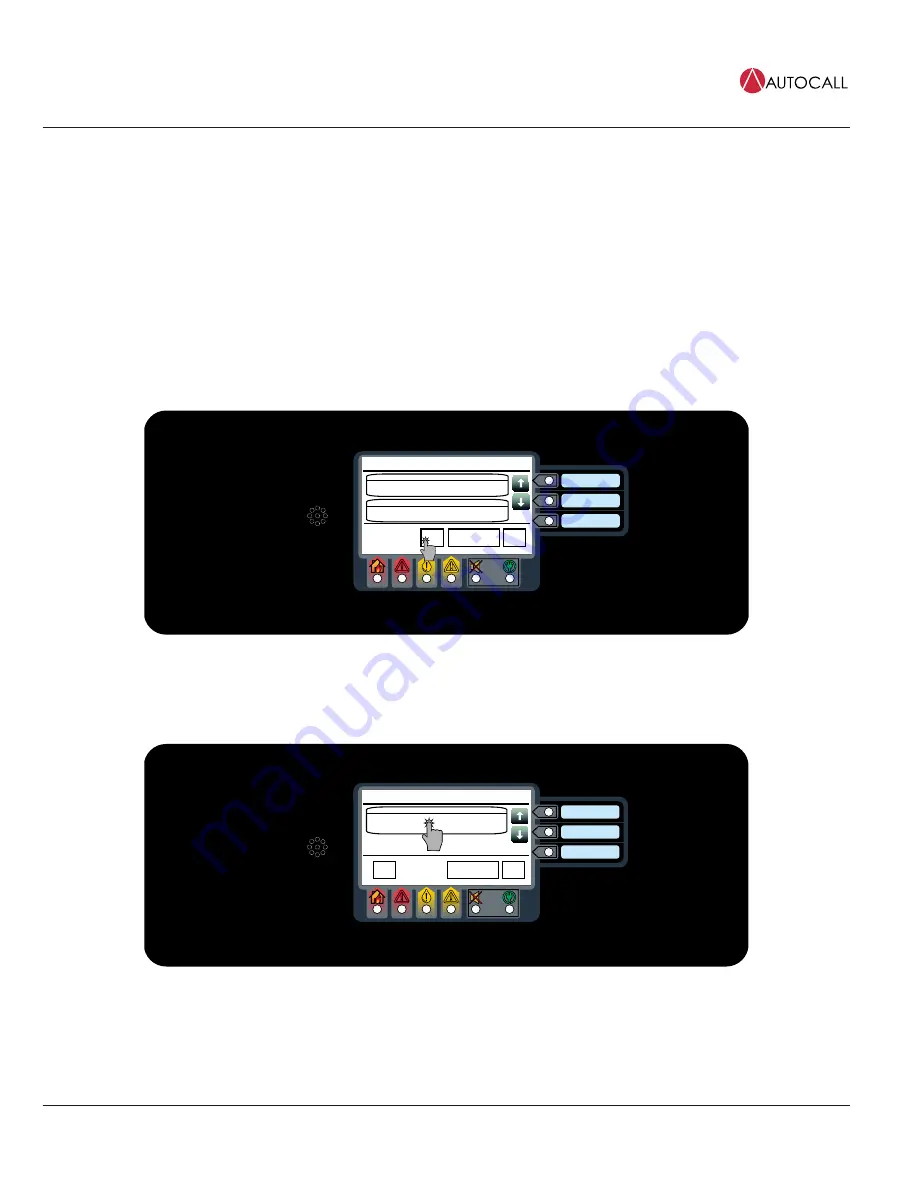
4.2.3 Global Acknowledge

Tap the 

ACK

 button.

Date

Time

Trouble in System

ACK

5

Alarm Functions

Menu

CARD 1, NAC POWER SUPPLY

NAC MISWIRE                          TROUBLE

Date

First of 5

SYSTEM TIME/DATE INVALID OR NOT SET

ABNORMAL

Date

Most Recent of 5

Fig 5: Acknowledge

4.2.4 Individual Acknowledge

Tap the unacknowledged alarm from the Zone Alarm List.

Date

Time

Fire Alarm in System

PULL STATION 1

FIRE ALARM

Date

First  of 1

Menu

Alarm Functions

ACK

1

Fig 6: Unacknowledged alarm

Note: 

The alarms that have not been acknowledged display the text 

Press to acknowledge

 on the top right of the button.

Содержание 4007ES

Страница 1: ...579 1165AC Rev C 05791165ACC 4007ES Operator s Manual ...

Страница 2: ...This page is intentionally blank ...

Страница 3: ... Trouble Conditions Details 13 6 Main Menu 14 6 1 Main Menu Screen Buttons 14 7 User Access Level 15 8 System Info 17 8 1 System Info Screen Buttons 17 8 1 1 Card Revisions 17 8 1 2 Software Revisions 17 8 1 3 Panel Serial Number 18 8 1 4 Card Status 18 8 1 5 System Files Info 18 8 1 6 IP Info 18 9 Panel Setup 19 9 1 Panel Setup Screen Buttons 19 9 1 1 Swap Config 19 9 1 2 Set Time Date 19 9 1 3 T...

Страница 4: ...lt Latch 26 13 9 NAC Miswire Test 26 13 10 Duplicate Device Search 27 13 11 Weak Answer Search 27 13 12 TrueAlert Test 27 13 13 TrueAlert NAC Test 28 13 14 CO Algorithms 28 13 15 Install Mode 28 13 16 NetDiag 29 14 Report Menu 30 14 1 Screen Buttons 30 ...

Страница 5: ...he limits for a Class A digital device pursuant to Part 15 of the FCC Rules These limits are designed to provide reasonable protection against harmful interference when the equipment is operated in a commercial environment This equipment generates uses and can radiate radio frequency energy and if not installed and used in accordance with the instruction manual may cause harmful interference to ra...

Страница 6: ...06 9205 are Color Touchscreen LCD Annunciators for 4007ES panels They provide remote annunciation of the FACP status Access to Annunciator switch functions can be enabled or locked using the keyswitch A maximum of six color touchscreen annunciators can be installed on a 4007ES panel Note The user interfaces for the 4007ES and the 4007ES Hybrid FACPs are identical and referred to collectively as 40...

Страница 7: ...s Bi color User Defined LEDs Associated with the three custom configured user buttons The top two LEDs can be either yellow or red The bottom LED can be either yellow or green Slide in Labels Used to describe the functions of the user buttons Fire LED Indicates a fire alarm when flashing and an acknowledged alarm when steady on Priority 2 LED Indicates a Priority 2 condition when flashing and an a...

Страница 8: ...ace displays the Fire Alarm in System screen which shows the list of all the triggered alarms The user interface displays the PRI2 Alarm in System screen which shows the list of all the triggered alarms Note A zone groups multiple points together and the Zone Fire and Zone PRI2 Alarms lists display all the zones where alarm conditions occurred You can view the points that triggered the alarms with...

Страница 9: ...idual Acknowledge Each zone inside the Zone Alarm list is acknowledged separately 4 2 3 Global Acknowledge Tap the ACK button Date Time Trouble in System ACK 5 Alarm Functions Menu CARD 1 NAC POWER SUPPLY NAC MISWIRE TROUBLE Date First of 5 SYSTEM TIME DATE INVALID OR NOT SET ABNORMAL Date Most Recent of 5 Fig 5 Acknowledge 4 2 4 Individual Acknowledge Tap the unacknowledged alarm from the Zone Al...

Страница 10: ...tton Date Time Fire Alarm in System PULL STATION 1 FIRE ALARM Date First of 1 Menu Alarm Functions ACK 1 Fig 7 Alarm functions button 2 Press the Alarm Silence button Fire Alarm in System System Reset USER BUTTON 1 USER BUTTON 2 USER BUTTON 3 Alarm Silence Fig 8 Alarm Silence button 3 Confirm the selection WARNING Ensure the evacuation of the building is completed prior to silencing the alarm Fig ...

Страница 11: ...ON 1 FIRE ALARM Date First of 1 Menu Alarm Functions ACK 1 Fig 10 Alarm functions button 2 Tap the System Reset button Fire Alarm in System System Reset USER BUTTON 1 USER BUTTON 2 USER BUTTON 3 Alarm Silence 100 Fig 11 System reset 3 Confirm the selection Fig 12 Confirm Note 1 If a zone or device has reset successfully the user interface returns to its normal display 2 If a zone or device remains...

Страница 12: ...te Time Fire Alarm in System PULL STATION 1 FIRE ALARM Date First of 1 Menu Alarm Functions ACK 1 Fig 13 Viewing the Alarm condition 2 Take the necessary actions using the buttons available at the point details screen A pull station point is shown as an example here M1 1 0 PULL STATION 1 Date Time Enable Disable M1 1 M1 1 PULL STATION DEVICE ADDRESS 2 1 TYPE ADRPUL IDNET2 CARD UNIT NUMBER 0 RUI NU...

Страница 13: ... begins to blink The Trouble LED begins to blink The piezo begins to sound a continuous tone The piezo begins to sound a continuous tone The user interface displays the Supervisory in System screen which shows the list of all the Supervisory conditions The user interface displays the Trouble in System screen which shows the list of all the Troubles Date Time Trouble in System ACK 5 Alarm Functions...

Страница 14: ...separately 5 4 Global Acknowledge Tap the ACK button Date Time Trouble in System ACK 5 Alarm Functions Menu CARD 1 NAC POWER SUPPLY NAC MISWIRE TROUBLE Date First of 5 SYSTEM TIME DATE INVALID OR NOT SET ABNORMAL Date Most Recent of 5 Fig 17 Acknowledge 5 5 Individual Acknowledge Tap the unacknowledged Trouble from the events list Date Time Trouble in System ACK 5 Alarm Functions Menu CARD 1 NAC P...

Страница 15: ... a point or a zone containing a variety of points A point in Trouble state is shown as an example Date Time Trouble in System ACK 5 Alarm Functions Menu CARD 1 NAC POWER SUPPLY NAC MISWIRE TROUBLE First of 5 SYSTEM TIME DATE INVALID OR NOT SET ABNORMAL Most Recent of 5 Press to acknowledge Press to acknowledge Fig 19 Trouble condition Take the necessary actions using the buttons available at the p...

Страница 16: ...ation of the basic components Alarm Log The Alarm Log screen contains the list of alarms that the panel has received Trouble Log The Trouble Log screen contains the list of Troubles that the panel has received Search Use the Search screen to look for any configured point on the system controlled by the panel System Reset Tap the System Reset button to reset all devices in alarm and clear all ackno...

Страница 17: ...Figure 25 shows functions with associated default user access levels 3 The ES Panel Programmer can be used to modify default user access levels for each function or set user access level passcodes Refer to document 579 1167AC 4007ES Panel Programmer s Manual for more details Fig 23 User access screen buttons User Access Level Current Access Level 1 Enter Passcode Logout 1 ABC 2 DEF 3 JKL 5 TUV 8 W...

Страница 18: ...ist 1 Verification Tally 1 TrueAlert Self Test 1 Main Menu 1 Function Name Default Access Level Show Alternate Config Version 2 Use Alternate Config 2 Location 3 IDNet 3 Last Result 3 TrueAlert ES Self Test 3 TrueAlert Device LEDs Test 3 TrueAlert Device Test Mode 3 TrueAlert Silent Test Mode 3 IViewMod 2 IAddMiss 3 IAddOpens 3 IRemvNorm 3 IRemvAll 3 Log Menu 1 Default Access Level Configured with...

Страница 19: ...ons Fig 26 System info screen buttons System Info Card Revisions Software Revisions Panel Serial Number Card Status USER BUTTON 1 USER BUTTON 2 USER BUTTON 3 Date Time System Files Info IP Info Fig 27 System info screen 8 1 1 Card Revisions Card Revision Information Appears Here Date Time Card Revisions 100 Tap the Card Revisions button to see a list of all the cards modules installed in the panel...

Страница 20: ...tatus button to see the status of the different cards installed in the panel 8 1 5 System Files Info BOOTLOADER REV 1 01 00 03 KERNEL REV 1 01 00 10 FILESYSTEM REV 1 01 01 15 PANELUI 1 01 02 16 System Files Info Date Time 100 Tap the System Files Info button to see the latest master revisions loaded on the Remote Annunciator 8 1 6 IP Info IP ADDRESS 192 168 1 150 HARDWARE ADDRESS 00 08 bd 01 dc 43...

Страница 21: ...UTTON 3 Date Time Tap the Swap Config button to access the following functions These functions allow roll back to the previous versions of the panel firmware Show Alternate Config Version Tap this button to display the previous version of the panel firmware Use Alternate Config Version Tap this button to install the previous version of the panel firmware 9 1 2 Set Time Date Day Month Year Hrs Mins...

Страница 22: ...s SnapShot Recovery Tap this button before doing a system upgrade to copy the software types currently loaded on the panel to the USB key To upload these software types back on the panel re insert the USB key in the USB Port of the 4007 CPU Card and tap the SnapShot Recovery button Eject USB Tap this button to safely remove the USB from the panel 9 1 5 System Upgrade Select All System Upgrade Chan...

Страница 23: ...on inside the Alarm Log screen 10 1 Alarm Log Screen Buttons Fig 30 Alarm Log buttons FIRE ALARM IN SYSTEM Menu Date Time First of 1 M1 30 0 Date Time FIRE ALARM Alarm Functions M1 30 0 PULL STATION ACK 1 100 Fig 31 Alarm Log Screen 10 1 1 Clear Clear 100 Tap the Clear button to erase all entries in the Alarm Logs screen IMPORTANT Use the Clear button only after the alarms have been investigated ...

Страница 24: ...red for each option inside the Trouble Log screen 11 1 Trouble Log Screen Buttons TROUBLE IN SYSTEM Menu Date Time First of 1 M1 17 0 Date Time M1 17 0 SUPPRESSION DETECTOR HEAD MISSING Alarm Functions ACK 1 100 Fig 32 Trouble Log Screen 11 1 1 Clear Clear 100 Tap the Clear button to erase all entries in the Trouble Logs screen IMPORTANT Use the Clear button only after the Troubles have been inves...

Страница 25: ...he IDNet button 2 Select the desired point number For example to select an IDNet point M1 1 0 enter 1 1 0 AUX ZONE SIG FB IO IDNet Pseudo Analog LIST ADDR New Search 3 1 2 4 5 6 7 8 9 0 M1 1 0 IDNet 100 Fig 35 Search screen Note Point numbers are first generated when the ES Panel Programmer is used to program points into the panel 3 Tap the Accept button to execute the search Tap the Erase button ...

Страница 26: ...SER BUTTON 2 USER BUTTON 3 CO Algorithms Install Mode Previous Page Date Time Net Diag Fig 38 Diagnostic screen 2 13 2 HW Reset Tap the Hardware Reset button to re initialize the state of certain hardware components A hardware reset is typically used to reset a Class A Trouble after the problem causing the Trouble is resolved Note If you attempt to perform a hardware reset without first fixing the...

Страница 27: ...nce button to access the Piezo Silence Menu screen where the On or Off buttons can be used to control the piezos at the panel and turn the Remote Annunciator s piezo on or off 13 6 Cfig Download Configuration Menu Enable Enable All USER BUTTON 1 USER BUTTON 2 USER BUTTON 3 Disable Revert Date Time Tap the Cfig Download button to access the Configuration Menu screen Inside the following functions a...

Страница 28: ...USER BUTTON 3 ViewRaw Date Time Tap the Earth Fault Latch button to access the Earth Latch Menu screen which can be used to latch intermittent earth fault Troubles to the panel This allows the panel to consistently display a Trouble instead of each time it re occurs The following functions are available Tap the Off button to disable the Earth Latch function Tap the On button to enable the Earth La...

Страница 29: ...s for TrueAlert addressable notification appliances can be performed The following functions are available TrueAlert Tests Menu TrueAlert ES Self Test USER BUTTON 1 USER BUTTON 2 USER BUTTON 3 TrueAlert Device LEDs Test TrueAlert Device Test Mode TrueAlert Silent Test Mode Date Time Tap the TrueAlert ES Self Test button and then use the Run Self Test button to run Self Test or use the View Test Re...

Страница 30: ...is is done to enhance the accuracy of A Vs measurement 13 14 CO Algorithms Tap the CO Algorithms button to access the IDNet CO Algorithms Menu screen The following functions are available IDNet CO Algorithms Menu Off On USER BUTTON 1 USER BUTTON 2 USER BUTTON 3 Date Time Tap the Off button to disable the IDNet CO Algorithms This is useful when smoke testing the IDNet CO devices Tap the On button t...

Страница 31: ...h network parameters to log and where these logs are saved Network Tallies Use this option to choose whether to view or clear network tallies Diag Tbls Missing Node Troubles Use this option to enable or disable missing node Troubles Diagnostic Message Options Use this option to select the node to which diagnostic messages are sent the message directions and the number of message retries Relay Mode...

Страница 32: ...uld not be found Refer to User Access Level on page 15 for access levels required to use each option inside the Report Menu screen 14 1 Screen Buttons Fig 39 Screen buttons AlarmLog Report Menu TroubleLog Status TrueAlarm Service TrueAlarm USER BUTTON 1 USER BUTTON 2 USER BUTTON 3 TrueAlert NAC Test TrueAlert Status TrueAlarm CO Active List Verification Tally TrueAlert Self Test Date Time Options ...

Страница 33: ...rueAlert Status button to access the Print TAlert Status screen The All button can be used to generate the report containing the status for all devices The Last button can be used to generate a report containing the status of the last test The report contains the following information Point ID Custom Label Pass Fail TrueAlarm CO Tap the TrueAlarm CO button to generate a report with the following i...

Страница 34: ...ditional listings may be applicable contact your local Autocall product supplier for the latest status Listings and approvals under Tyco Fire Security GmbH and the product names listed in this material are marks and or registered marks Unauthorized use is strictly prohibited NFPA 72 and National Fire Alarm Code are registered trademarks of the National Fire Protection Association NFPA ...

Отзывы: