background image

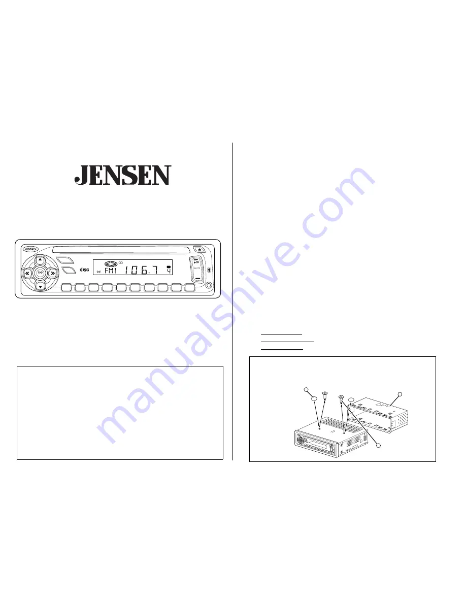
Remove transport screws

Quite los tornillos transportadores

Enlevez les vis de transport

Remove half sleeve

Quite la media camisa

Enlevez le demi-fourreau

Place adhesive dots

Ponga los puntos adhesivos

Collez les pastilles adhésives

2

1

3

COM

PAC

T

DIG

ITAL

AUD

IO

PWR

VOL

VOL

SEL

BAND

AUX

MUTE

RPT

1

RPT

A-B

2

RDM

3

INT

4

5

MEM/CLR

6

ELAPSE

AS/PS

BASS

SCAN

DISP

CH

PROGRAM

RPT

INT

AM/FM

/CD RE

CEIVER

CD3210

45W

x 4

RDM

PGM

AUX

COMPACT

DIGITAL AUDIO

PWR

VOL

VOL

SEL

BAND

AUX

MUTE

RPT

1

RPT A-B

2

RDM

3

INT

4

5

MEM/CLR

6

ELAPSE

AS/PS

BASS

SCAN

DISP

CH

PROGRAM

RPT

INT

AM/FM/CD RECEIVER

CD3210

45W x 4

RDM

PGM

AUX

CD3210

Owner’s Manual

Thank You!

Thank you for choosing a Jensen product. We hope you will find the instructions in this owner’s 
manual clear and easy to follow. If you take a few minutes to look through it, you’ll learn how to 
use all the features of your new Jensen receiver for maximum enjoyment.

Preparation. . . . . . . . . . . . . . . . . . . . . . . . . . . . . . . . . . . . . . . . . . . . . . . . . . . . . . . . . . . . . . .  1
Wiring . . . . . . . . . . . . . . . . . . . . . . . . . . . . . . . . . . . . . . . . . . . . . . . . . . . . . . . . . . . . . . . . . . .  3
Installation . . . . . . . . . . . . . . . . . . . . . . . . . . . . . . . . . . . . . . . . . . . . . . . . . . . . . . . . . . . . . . .  5
Basic Operation . . . . . . . . . . . . . . . . . . . . . . . . . . . . . . . . . . . . . . . . . . . . . . . . . . . . . . . . . . .  6
Tuner Operation. . . . . . . . . . . . . . . . . . . . . . . . . . . . . . . . . . . . . . . . . . . . . . . . . . . . . . . . . . .  9
CD Player Operation . . . . . . . . . . . . . . . . . . . . . . . . . . . . . . . . . . . . . . . . . . . . . . . . . . . . . .  . 11
Remote Control . . . . . . . . . . . . . . . . . . . . . . . . . . . . . . . . . . . . . . . . . . . . . . . . . . . . . . . . . . . 12
Troubleshooting  . . . . . . . . . . . . . . . . . . . . . . . . . . . . . . . . . . . . . . . . . . . . . . . . . . . . . . . . . . 13
Specifications  . . . . . . . . . . . . . . . . . . . . . . . . . . . . . . . . . . . . . . . . . . . . . . . . . . . . . . . . . . . . 13
Warranty . . . . . . . . . . . . . . . . . . . . . . . . . . . . . . . . . . . . . . . . . . . . . . . . . . . . . . . . . . . . . . . . . 13

Preparation

Getting Started

It’s a good idea to read all of the instructions before beginning the installation.

Tools and Supplies

The following tools and supplies are needed to install the radio.

Torx type, Flat and Phillips screwdrivers

Wire cutters and strippers

Tools to remove existing radio (screwdriver, socket wrench set or other tools)

Electrical  tape

Crimping tool

Volt meter/test light

Crimp connections

18 gauge wire for power connections

16-18 gauge speaker wire

Speaker Requirements: Only connect speakers rated in the load impedance of 4 ohms. 
Speakers with a load impedance less than 4 ohms could damage the unit.

Disconnect Battery

Before you begin, always disconnect the battery negative terminal.

Prepare Radio

1.

Remove half sleeve - Lift latches on both sides to remove half-sleeve from radio.

2.

Remove transport screws - Remove screws before inserting a CD.

3.

Place adhesive dots - Press adhesive dots over transport screw holes.

Audiovox Electronics Corporation

150 Marcus Boulevard

 Hauppauge, NY 11788

1-800-323-4815

www.jensen.com

 © 2004 Audiovox

v.111103

Prepare Radio

Preparar la Radio
Préparer la Radio

Содержание Jensen CD3210

Страница 1: ...r Operation 11 Remote Control 12 Troubleshooting 13 Specifications 13 Warranty 13 Preparation Getting Started It s a good idea to read all of the instructions before beginning the installation Tools a...

Страница 2: ...de calibre 16 a 18 Requerimientos del altavoz Solamente conecte los altavoces de carga de impudencia de 4 ohms Altavoces con una carga de impedancia menor a los 4 ohms pueden da ar la unidad Desconect...

Страница 3: ...being in the car 1 Splice or crimp wires 2 Attach wiring adapter to car wiring harness Wiring Diagram Color Codes 1 RCA to RCA cables not supplied 2 Amplifier wiring see amplifier instructions 3 Powe...

Страница 4: ...r hacer la reconexi n de la bater a a la terminal negativa de la misma Pr paration continu Installation du demi manchon 1 Installez l adaptateur si n cessaire facultatif 2 Installez le demi fourreau d...

Страница 5: ...ice el chasis del radio en la media camisa 4 Asegure el radio al soporte usando una tuerca si es posible 5 Ponga en su lugar cualquier art culo que haya quitado del tablero de instrumentos Instalaci n...

Страница 6: ...enciar al receptor 4 Intensidad Pulse BASS 4 para aumentar el tono del bajo BASS aparece en el visualizador cuando se lo activa 5 Pitido Audible Presione SEL 5a por tres segundos para encender o apaga...

Страница 7: ...os altavoces derecho e izquierdo desde R12 completamente a la derecha a L12 completamente a la izquierda C00 representa un balance de nivel igual Atenuaci n Ac stica Presione SEL 5a cinco veces y util...

Страница 8: ...t puesta en frecuencia el visualizador muestra el n mero de la pista del CD o el tiempo transcurrido dependiendo de la actual opci n de visualizaci n seleccionada para el CD Presionando el bot n DISP...

Страница 9: ...ntinuar a la siguiente estaci n autom ticamente 12 Rastreo Presione SCAN 12 para rastrear las emisoras de se al fuerte de la banda actual La radio hace pausa por cinco segundos en cada emisora de se a...

Страница 10: ...leccione seis emisoras de se al fuerte y almac nelas en la banda actual 1 Seleccione una banda si fuera necesario 2 Mantenga pulsado el bot n la AS PS 14 en forma continua por m s de 3 segundos Las em...

Страница 11: ...16 Pausa Pulse el bot n de pausa para dar pausa a la reproducci n del CD 17 Salto de Pistas Salto de Pistas Pulse el bot n o 17a y 17b por menos de un segundo para avanzar a la siguiente pista del CD...

Страница 12: ...o de la pista en la memoria del equipo En el visualizador aparece el n mero siguiente de pista 2 Contin e hasta ocho veces para hacer la selecci n de todas las pistas deseadas 3 Pulse PGM 21b para rep...

Страница 13: ...ower supply 11 16 VDC negative ground Speaker output impedance 4 Ohms Fuse 10 amp fast blow ATO Dimensions 7 x 7 x 2 178mm x 178mm x 55mm Specifications subject to change without notice 12 Month Limit...

Страница 14: ...i n AM Alcance de sintonizaci n 530 kHz 1720 kHz Amplificador Capacidad total de corriente 180W pico Salida de corriente 45 W x 4 General Suministro de corriente 11 16 VDC negativo a tierra Impendanci...

Страница 15: ...teur MA Gamme de fr quences 530 KHz 1720 KHz Amplificateur Puissance totale du syst me 180 watts pointe Puissance de sortie 45 W x 4 G n ralit s Alimentation 11 16 volts c c mise la terre n gative Imp...

Отзывы: