Phone 425-775-8461 • Fax 425-778-3166
®
13
tm
C
OMPONENT
V
IDEO
I
NPUTS
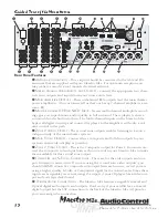
- Component video is one of the highest quality for-
mats available. Use it whenever possible.
C
OMPONENT
V
IDEO
O
UTPUT
– Connect these high quality video outputs to your
main video display device (ie. Projector, CRT, LCD, etc.) You will be pleased to know
that they will convert the Composite and S-video signals to the Component outputs
of your Maestro M2e. See page 20 for more details.
12 V
OLT
T
RIGGER
O
UTPUTS
- These three outputs provide a +12 volt signal to
control the power amplifiers, source units, video projector, screens and curtains in
the theater. The Main Trigger output is active whenever the Maestro is turned on;
the Video Trigger 2 is active whenever a video source is selected.
IR R
EMOTE
C
ONTROL
C
ONNECTIONS
- These jacks enable use of external IR sensors
and emitters for installations where it is not desireable to use the front panel IR
sensor.
HDMI I
NPUTS
& O
UTPUTS
– These inputs allow the Maestro M2e to accept digital
video signals from source units equipped with HDMI (High Definition Multimedia
Interface) outputs. The Maestro M2e outputs digital signals via this HDMI output to
a projection device with an HDMI input.
A
CTIVE
B
ALANCED
O
UTPUTS
– This conveniently located RJ-45 connector outputs
component video signals
PLUS
digital audio
OR
remote power that then runs to an
optional AudioControl BVR-25 balanced line receiver. The switch next to the LED
allows you to select between digital audio or remote power. Hint - Bright red LED
means Remote Power. These outputs run in parallel to the Maestro M2e’s standard
component outputs so you will want to make sure that these component outputs
(YUV) are activated in the General Settings menu (see page 25).
RS-232 S
ERIAL
P
ORT
- This connection is used to interface the Maestro with an
external touch-screen or other automation system. It is also used when updating
the internal Maestro M2e firmware programming.
G
ROUND
L
IFT
S
WITCH
- In complex home theater systems, ground loops can be a
painful fact of life. This button isolates the signal ground connections on the Mae-
stro M2e from the AC Power ground. For safety reasons, the chassis remains earth
grounded at all times.
M
AIN
P
OWER
C
ONNECTION
- All good AC power flows in here.
M
AIN
P
OWER
S
WITCH
– Think of this as the vacation switch. You should only need
to turn off your Maestro M2e with this button when the system will not be used for
some time. Normally this button is left on and the Maestro M2e is “woken up” via
the “Standby” switch on the front panel, via the optional remote control or through
an automation system. When this switch is turned off, you cannot turn the Maestro
M2e on of off via any other method.
B
ALANCED
A
UDIO
O
UTPUTS
– These outputs send signals to amplifiers with bal-
anced XLR type inputs. This type of configuration yields maximum noise rejection
from the airborne interference and is recommended for applications where you are
sending audio signals over a long distance.
Guided Tour of the Masestro
M2e
Содержание Maestro M2e
Страница 2: ......
Страница 4: ...Phone 425 775 8461 Fax 425 778 3166 4 tm This page was intentionally left blank Please enjoy it ...
Страница 14: ...Phone 425 775 8461 Fax 425 778 3166 14 tm Guided Tour of the MasestroM2 ...
Страница 18: ...Phone 425 775 8461 Fax 425 778 3166 18 tm MaestroM2etm Set Up Configuration ...
Страница 50: ...Phone 425 775 8461 Fax 425 778 3166 50 tm ...
Страница 54: ...Phone 425 775 8461 Fax 425 778 3166 54 tm ...


