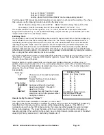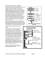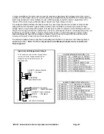
DPX16: Instructions for Basic Operation and Installation
Page 26
RS-232 R
EMOTE
C
ONTROL
I
NTERFACE
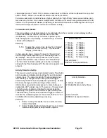
The DPX16 has a built in RS-232 serial interface, which supports remote control of the DPX16 through
simple ASCII commands. These commands provide access to the front panel button operations just as
the IR Remote Control does.
The DPX16 serial interface is fixed at 9600 baud, 8 bits, 1 stop bit, and no parity. The command format is:
<command> <return>
The command is 2 characters or 2 characters plus parameter and must be followed by a “carriage return”.
The DPX16 will respond with:
>
if the command was recognized, or
?
if the command was not recognized or is invalid
The following commands are supported by the DPX16 serial interface:
BD
Display Button
BS
Sequence Button - will cause DPX16 to begin sequencing
BP
Pip Button
BQ
Quadrant Button
BV
VCR Button - will cause the DPX16 to enter or exit VCR playback mode or “zoom out”
BF
Freeze Button - will cause the DPX16 to freeze current display video
BB
VCR Bypass - will cause the DPX16 to enter or exit the VCR bypass mode
BZ
Zoom Button - will cause the DPX16 to enter Zoom mode or “zoom in” in Zoom mode
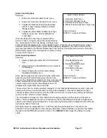
BCn
Camera Button - n is a number 1 through 16 corresponding to the camera number. There
must be no “space” or “tab” entered between the command and the number.
BL n
Button Lock - n=0 sets front panel button lock OFF, and n=1 sets button lock ON.
CM
Call Monitor - will cause the DPX16 to toggle between “Normal” and “Call Monitor” modes.
When in “Call Monitor” mode, button commands will control Call Monitor functions.
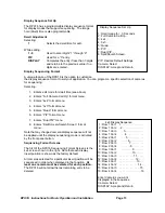
DM m,c,c,c,...,q
Set Display Mode - will cause the DPX16 to enter the selected display mode with selected
cameras in the display inserts where m=display mode, c=camera number, q=quadrant.
Display modes are as follows: 0=Full screen, 1=2x2, 2=3x3, 3=4x4, 4=PIP, 5=Dual PIP,
6=Split screen, 7=Squish screen.
EC n
Echo characters - n=0, echo OFF; n=1, echo ON (factory default).
HELP
Help command - will display a list of commands.
MD
Move Down - in Zoom mode, will cause the DPX16 display to move down.
ML
Move Left - in Zoom mode, will cause the DPX16 display to move left.
MR
Move Right - in Zoom mode, will cause the DPX16 display to move right.
MU
Move Up - in Zoom mode, will cause the DPX16 display to move up.
VER
Version - will cause the DPX16 to output the current software version number.
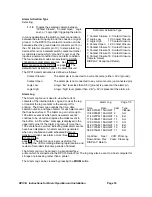
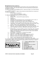
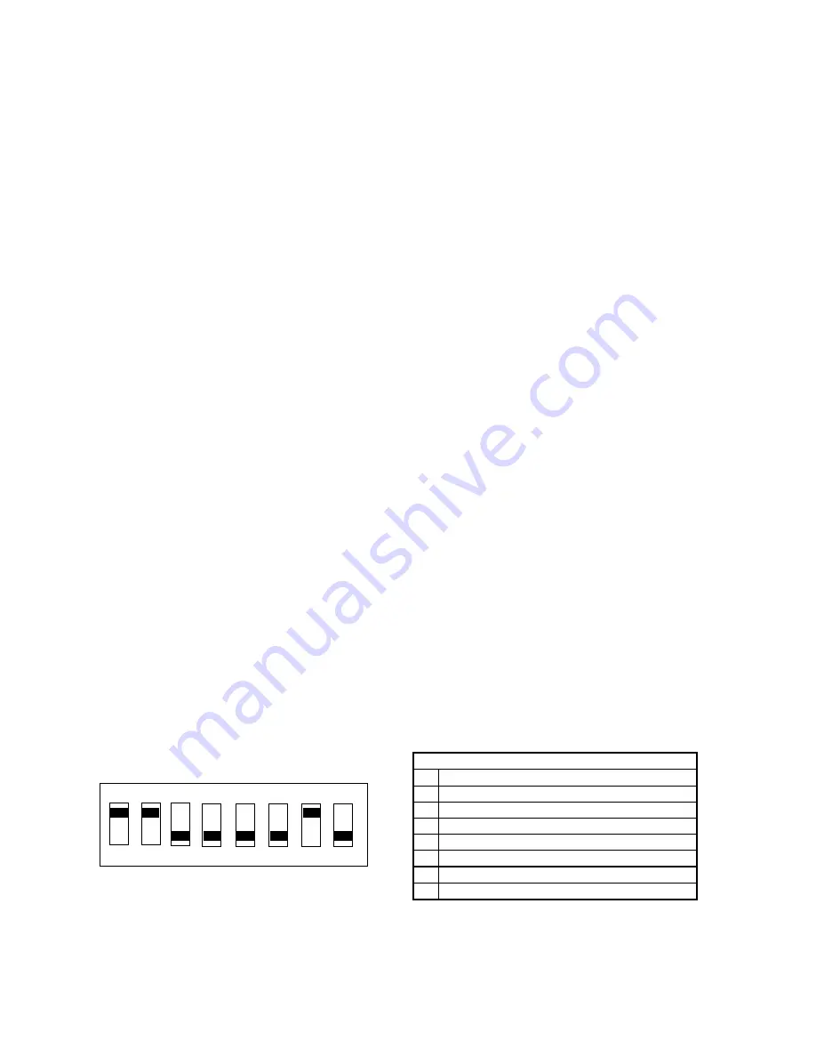
For proper RS-232 operation, the 8 position DIP switch, SW 1, located next to the RJ-45 RS-232 interface
connector within the DPX16 must be set to the factory default positions as indicated below. The RJ-45
connector pin-out corresponds to a standard
EIA-561 8-pin DCE (modem) device.
SERIAL CONNECTOR PINS
1
Signal ground
2
Signal ground
3
Signal ground RS232, Open RS422
4
Signal ground
5
TX+ (out) RS232 or 422
6
RX+ (in) RS232 or 422
7
Open RS232, RX- (in) RS422
8
Open RS232, TX- (out) RS422
O N
4
2
5
3
6
7
8
1
S W 1

