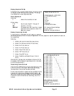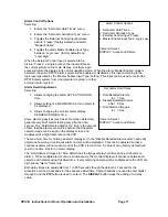
DPX16: Instructions for Basic Operation and Installation
Page 18
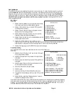
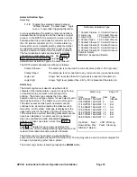
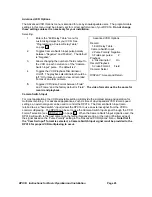
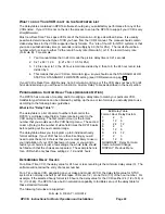
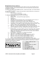
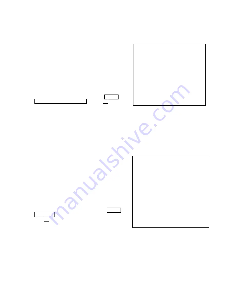
Alarm Activation Type
Selecting:
1 - 16
Toggles the selected camera between
“Contact Closure”, “Contact Open”, “Logic
Low”, or “Logic High” triggering the alarm.
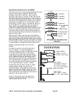
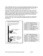
In many applications the switch contact connection is
between the alarm input pin and the chassis or signal
ground. In the DPX16 the contact connection can be
between either the ground (alarm connector pin 15) or
the +5V (alarm connector pin 13). In some alarming
devices this is not a metallic switch contact but rather
a solid state device which “grounds” (Logic Low) the
input as a normal condition or as an alarm condition.
The four activation modes are provided to simplify
connection to most alarm sources. See “Alarm
Interconnection on the DPX16” on page 24. The
default Alarm Activation Type is “Contact Closure”.
The DPX16 alarm activation is defined as follows:
Contact Closure:
The alarm pin is connected to a current source (5V or ground).
Contact Open:
The alarm pin is not connected to any current source (unconnected pin).
Logic Low:
A logic “low” level less than 0.8V (ground) is present at the alarm pin.
Logic High:
A logic “high” level greater than 2.4V (+5V) is present at the alarm pin.
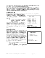
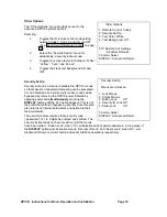
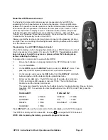
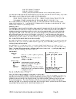
Alarm Log
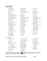
The Alarm Log menu is used to view the current
contents of the internal Alarm Log and to clear the log
or transmit the log contents to the serial port for
printing. The Alarm Log contains the time, date,
camera number, and type of alarm for each alarm event
that has been stored. The Alarm Log can store up to
100 alarm events at which point new alarm events
continue to be stored and replace the oldest event in
the buffer. An “Overflow” message is displayed in the
upper left corner of the Alarm Log menu if more than
100 events have occurred indicating older alarm events
have been displaced. An alarm event is generated
when any enabled and valid scheduled External,
Activity, or Video Loss alarm occurs (See “Alarm
Scheduling” on
page 15). The Alarm Log is a very useful tool for
reviewing the VCR recording allowing rapid location and
review of recorded video time periods of interest.
The Alarm Log may be printed on a serial interface
printer which is connected to the DPX16 Serial Port. The log may also be sent to a host computer for
storage or processing rather than a printer.
The Alarm Log can be cleared by pressing the ZOOM button.
Set Alarm Activation Type
1: Contact Closure 9: Contact Closure
2: Logic Low 10: Contact Closure
3: Logic High 11: Contact Closure
4: Contact Open 12: Contact Closure
5: Contact Closure 13: Contact Closure
6: Contact Closure 14: Contact Closure
7: Contact Closure 15: Contact Closure
8: Contact Closure 16: Contact Closure
Camera: Select
DISPLAY: Accept and Return
Alarm Log
Page 1/5
Time Date Cam Type
09:49:27AM 15AUG97 1 VidLoss
10:40:28AM 16AUG97 2 Act
11:49:27PM 16AUG97 16 Ext
11:52:00AM 16AUG97 11 Act
12:02:57AM 16AUG97 10 Act
01:20:15AM 16AUG97 16 Ext
06:01:37AM 16AUG97 16 Ext
06:02:15AM 16AUG97 11 Act
Up Arrow: Next VCR: Print Log
Down Arrow: Prev Zoom: Clear Log
DISPLAY: Return


