52
Atmel AVR2052
8200M-AVR-11/11
12.3 Pre-built images
The SDK comes with a set of ready-to-use binary images of the WSNDemo
application. It includes a set of images for different roles, which are preconfigured with
distinct MAC addresses so they can be used for creating a small ZigBee network right
away. The iImage name is formed according to the following scheme:
WSNDemo_<role>_<rf_chip>_<region>.<extension>
To specify node role, put
Coord
,
Router
, or
EndDev
for coordinator, router, and end
device, respectively.
Region
is an optional parameter that specifies the radio
frequency used by the image according to the frequency band of the specified region.
Possible options are
US
,
EU
, and
China
. For example, to use JTAG to program an
Atmel AT91SAM7X-EK device with an RF212 radio acting as coordinator for use in
the US, use the file with the name
WSNDemo_Coord_Rf212_US.bin
NOTE
Default images are preconfigured to use Extended PAN ID
0xAAAAAAAAAAAAAAAA
and
operate on channel
0x0F
(for RF231 and RF230 radios) or channel
0x01
and channel
page 0 (for RF212 radio).
12.4 Running WSNDemo
12.4.1 Starting WSNDemo
To run WSN Demo application, proceed as follows:
1. Set up the hardware, as described in Section
2. Install the Atmel BitCloud SDK, as described in Section
3. Program one device with the coordinator image file and other with either the
router or end device images, as described in Section
4. Connect the AT91SAM7X-EK #1 (coordinator) to the PC USB port.
5. Run WSNMonitor (see Section
6. Power on and reset the rest of the nodes.
12.4.2 Monitoring WSNDemo activity
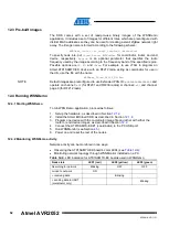
Network activity can be monitored in two ways:
•
Observing the AT91SAM7X-EK board’s color LEDs (see
•
Monitoring network topology through WSNMonitor installed on a PC.
Table 12-4.
LED indication for AT91SAM7X-EK boards used in WSNDemo.
Node state
LED1 (red)
LED2 (yellow)
LED3 (green)
Searching for network
Blinking
OFF
OFF
Joined to network
ON
+ receiving data
Blinking
+ sending data to UART
(coordinator only)
Blinking


