Atmel AVR2052
35
8200M-AVR-11/11
•
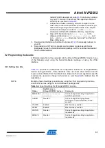
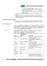
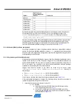
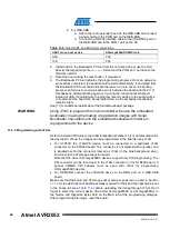
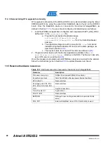
Monitoring the network topology through WSNMonitor installed on a PC (see
Section
Table 9-6.
LED indication for RCB128A1 (and ATAVR128RFA1-EK1) boards used in
WSNDemo.
Node state
LED D2 (red)
LED D3 (yellow)
LED D4 (green)
Searching for network
Blinking
OFF
OFF
Joined to network
ON
+ receiving data
Blinking
+ sending data to UART
(coordinator only)
Blinking
Sleeping (end device only)
OFF
OFF
OFF
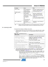
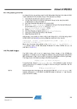
9.4.3 Demonstrating OTA upgrade functionality
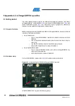
OTA upgrade functionality of the BitCloud SDK can be demonstrated using the
megaRF platform by using the serial Atmel DataFlash device found on the STK600
board. Once the DataFlash device is connected to the Atmel ATmega128RFA1, as
the user should configure and install devices as follows:
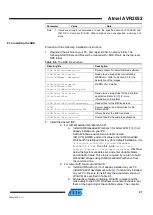
1. Load the WSNDemo application configured and compiled with
APP_USE_OTAU
defined as 1 in the
configuration.h
file:
a. Program the embedded bootloader
bootloaderOTAU_ATmega128RFA1.hex
file from the Serial
Bootloader package.
b. The application image should be converted to
*.srec
format and
installed using the Bootloader PC tool from the same package, as
described in Section
c. The device is able to act as an OTA client, as defined in
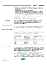
2. Program another device with the Runner application, which is available in the
<SDK-Root>\Evaluation Tools\Runner\
directory of the SDK. The Runner
node acts as OTA server, as defined in
Once the images are programmed and WSNDemo devices are joined to the network,
follow the instructions given in Section
to update firmware over the air.
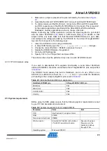
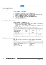
9.5 Reserved hardware resources
Table 9-7.
Hardware resources reserved by the stack on ATmega128RFA1.
Resource
Description
Processor main clock
8MHz from internal RC oscillator
TRX24
Radio
ATmega ports PG3, PG4
Asynchronous timer interface
Timer/Counter 2
Asynchronous timer
Timer/Counter 4
System timer
External IRQ4
Wake up on DTR
EEPROM
Storage for user settings accessible via persistent data server
PE0..PE2, PG5
External DataFlash, when OTAU functionality is used

