9
ATAN0080 [APPLICATION NOTE]
9341B–AVR–02/15
4.
Peripherals
4.1
QTouch Sensors
The QTouch algorithms enable either the three QTouch buttons or the QTouch slider to be used.
Obviously, the software used should match the connected sensors. The software shipped with the kit uses the slider in
stand-alone mode. To evaluate the use of the buttons in stand-alone mode, the source initializing the touch functionality
located in the main.c file must be changed.
/* Init Touch */
AtaDevTouch_init(QT_SENSOR_SLIDER);
qt_sensor_flag = QT_SENSOR_STATE_SLIDER;
to
/* Init Touch */
AtaDevTouch_init(QT_SENSOR_BUTTONS);
qt_sensor_flag = QT_SENSOR_STATE_BUTTONS;
Alternatively, the GUI-connected mode can be used to evaluate the buttons as described in
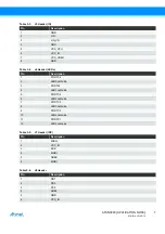
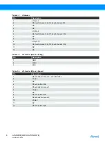
. The jumpers on header J15 must be connected as shown below to use the CS2 to CS4 QTouch buttons.
The jumpers on header J15 must be connected as shown below to use the CS1 QTouch slider.
In either method, the following pins on the J9 header must be connected: 1-2, 5-6, 9-10.
4.2
LEDs
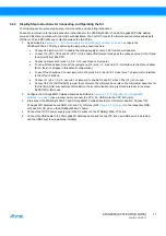
Six LEDs can be used to display the status of the application. The relevant headers are J6 and J1. To use the LEDs, the pins
on the J6 header must be connected 1-2, 3-4, etc. To use the LED2 and LED3, it is also necessary to connect the jumpers
on pins 2-4 and 1-3 on the J1 header so that the Atmel
®
ATtiny1634 MCU port can be connected directly to the LEDs. The J1
header must be configured correctly to enable PC4-LED2 and PC5-LED3 connections; alternatively, the J1 header can be
used to supply an external oscillator or a clock to the microcontroller.
LED5 can only be used if the J12 autobaud jumper is not mounted and the autobaud feature is disabled. This requires
recompiling the software or using the GUI to deactivate autobaud.
4.3
Potentiometer
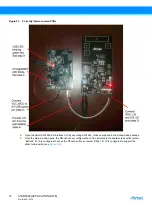
A potentiometer can be connected to an Atmel ATtiny1634 MCU port pin to evaluate the ADC. The potentiometer is
connected to VCC_IO and GND, resulting in the full ADC range being used when AREF=VCC_IO is used. Jumper J14 has
to be mounted to use the potentiometer.
Table 4-1.
J15 Header in Button Configuration
J15 Header Pins
Pin 2 – Pin 4
Pin 6 – Pin 8
Pin 10 – Pin 12
Table 4-2.
J15 Header in Slider Configuration
J15 Header Pins
Pin 1 – Pin 2
Pin 5 – Pin 6
Pin 9 – Pin 10

