3
ATAN0080 [APPLICATION NOTE]
9341B–AVR–02/15
2.
Getting Started
2.1
Quick Start
There are several ways to supply power to the kit.
2.1.1
Kit Power Supply via a VBat Supply Voltage
This is the easiest way to supply the kit with power. When using this method, please note that power for the entire board is
supplied by the Atmel
®
ATA663254 LIN SBC and is therefore limited to a maximum of 85mA. The following steps ensure
correct functionality:
1.
Mount the J2, J3, and J11 jumpers.
2.
Connect the 12VDC power supply plug to the X2 power input socket on the ATABtiny1634A-V1 PCB to supply the
board with power.
2.1.2
Supplying Power to the MCU and the LIN SBC Independently
This power supply variant allows more current to be driven than is available from the LIN SBC by supplying the current from
an externally regulated 5VDC power supply.
1.
Mount the jumper J11 (if the transceiver is to be used).
2.
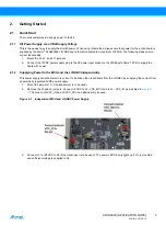
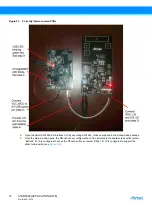
Remove the J2 and J3 jumpers. C5VDC to J2 - VCC_MCU and to J3 - VCC_IO as indicated in
. The pins on J5/VCC_IO and J5/VCC_CPU can alternatively be used.
Figure 2-1.
Independent MCU and LIN SBC Power Supply
3.
C7 to +28VDC to X2 (if the transceiver is to be used). The power LED D8 only lights up if J11 is mounted
and sufficient voltage is supplied to X2.

