background image

ATAN0080 [APPLICATION NOTE]

9341B–AVR–02/15

2

1.

Introduction

1.1

Kit Overview

The Atmel

®

 ATAtiny1634-EK1 automotive evaluation kit provides a hardware platform for evaluating the Atmel ATtiny1634 

automotive MCU and Atmel ATA663254 SBC and for developing software for the Atmel ATtiny1634 MCU. The Atmel 
ATtiny1634 is a high-performance, low-power AVR

®

 microcontroller with 16KB of in-system self-programmable Flash 

memory and 1KB of internal SRAM designed specifically for automotive applications. The ATABtiny1634A board included in 
the kit interfaces the ATtiny1634 MCU to different types of I/O signals. The board also provides interfaces to several 
capacitive touch buttons and one capacitive touch slider as well as six LEDs and a potentiometer. The Atmel ATA6632 SBC 
integrating the LIN transceiver along with a voltage regulator and a watchdog enables the LIN bus functionality. In addition to 
the variety of I/Os provided directly on the board, all MCU I/O signals are made available on the header pins to support easy 
connection to external I/Os. When combined with available embedded software, the ATABtiny1634A board is an ideal 
platform for initial development of customer-specific applications.

To facilitate the connection to a LIN bus, the kit includes an ATmega64-M1 Xplained board programmed to act as a 
USB-to-LIN gateway. Using this gateway, the ATABtiny1634A board can be connected to an available PC GUI application to 
monitor and control the on-board I/Os. More generally, the PC GUI application could be used along with the gateway board 
to simulate LIN master traffic to aid in the development of an ATABtiny1634A board LIN slave application.

This kit is supported by standard Atmel AVR development tools available at 

http://www.atmel.com/design-support/software-tools/default.aspx.

The kit offers a set of features that enables the user to get started right away and gain an understanding of how to integrate 
the ATtiny1634-EK and the Atmel ATA663254 within their own design.

Figure 1-1.

ATABtiny1634A_V1 PCB 

Содержание ATtiny1634-EK1

Страница 1: ...gital I O Six user LEDs Various headers for direct access Two possible power sources for the Atmel ATtiny1634 MCU Voltage regulator of the Atmel ATA663254 SBC External 5V header Connectivity LIN Bus K...

Страница 2: ...f I Os provided directly on the board all MCU I O signals are made available on the header pins to support easy connection to external I Os When combined with available embedded software the ATABtiny1...

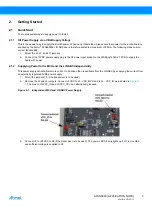
Страница 3: ...nput socket on the ATABtiny1634A V1 PCB to supply the board with power 2 1 2 Supplying Power to the MCU and the LIN SBC Independently This power supply variant allows more current to be driven than is...

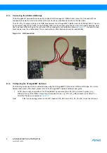
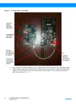
Страница 4: ...ng the connections as shown in Figure 2 2 the outer red and black cables cross the middle cable The pin descriptions on the silkscreen should be read carefully Figure 2 2 LIN Connection 2 1 4 Configur...

Страница 5: ...ntaining schematics BOM assembly drawings 3D plots layer plots software etc 2 Atmel Studio http www atmel com atmelstudio free Atmel IDE for development of C C and assembler code for Atmel microcontro...

Страница 6: ...ve node J5 J5 1x8 connects ATABtiny1634A V1 PCB to external power supply VCC LIN_VS GND LIN IO pin VCC_VREG and external power supplies VCC_MCU VCC_IO J6 J6 2x6 connects the Atmel ATtiny1634 IO ports...

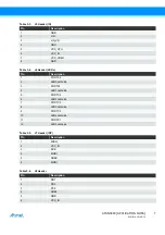
Страница 7: ...Table 3 4 J6 Header LEDs Pin Description 1 PORTC2 2 LED0 cathode 3 PORTA1 4 LED1 cathode 5 PORTC4 6 LED2 cathode 7 PORTC5 8 LED3 cathode 9 PORTC0 10 LED4 cathode 11 PORTC1 12 LED5 cathode Table 3 5 J7...

Страница 8: ...NC 8 NC 9 J15 pin 10 10 R3 touch channel 0 K C8 touch channel 0 S 11 NC 12 NC Table 3 8 J13 Header QTouch Debug Pin Description 1 GND 2 MOSI 3 SCK Table 3 9 J15 Header QTouch Sensor Pin Description 1...

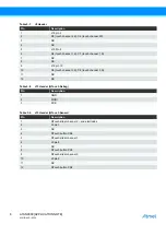
Страница 9: ...9 10 4 2 LEDs Six LEDs can be used to display the status of the application The relevant headers are J6 and J1 To use the LEDs the pins on the J6 header must be connected 1 2 3 4 etc To use the LED2 a...

Страница 10: ...stem functionality can be summarized as follows ATmega64M1 Xplained PCB is used as the LIN bus gateway and LIN bus master It uses the USB port to communicate with the host PC It also uses the LIN bus...

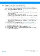
Страница 11: ...0 to interface to the QTouch slider Note the kit is shipped in this default configuration To use QTouch buttons Connect jumpers to J15 pins 2 4 6 8 and 10 12 use three 1x2 jumpers to interface to the...

Страница 12: ...UI by executing ATA1634_GUI exe supplied in the kit download package 7 Once the main window opens the QTouch sensor configuration can be selected in the board setup section select Buttons if J15 is co...

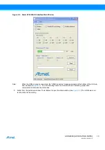
Страница 13: ...ted the USB Connected message appears at the bottom of the GUI win dow as shown in Figure 5 2 The incrementing frame count is also shown indicating proper data communication between the LIN nodes 8 Se...

Страница 14: ...ble and restart the GUI application to reset the PCB USB LED must flash green red and the LED0 must alternate between ON and OFF 10 During normal operation the LIN frame counters should increment whil...

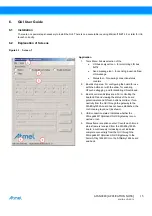
Страница 15: ...ith the slider for enabling QTouch debugging and for disabling LIN autobaud 3 Board control and status area For controlling the board LEDs and viewing the status of the board potentiometer and QTouch...

Страница 16: ...to control the ATABtiny1634A board LEDs the LEDs on the board will correspond to the selection on the GUI assum ing the board jumpers are properly configured 4 Potentiometer status Follows the potenti...

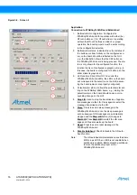
Страница 17: ...a 4 Stop Press to stop message logging changes to start after being pressed 5 Start Press to start message logging changes to stop after being pressed The default software supports 2 LIN message frame...

Страница 18: ...dly or once only single shot Periodic messages are continuously sent until stopped by the user or until this window is closed 4 Used to select between subscribe and publish 5 Send Press to send the me...

Страница 19: ...AVR 02 15 Figure 6 5 Screen 5 Status Tool 1 Launch from the application tools menu Connec tion status 2 Displays USB connection status connection time approximately in seconds and various counters 3...

Страница 20: ...1 4 Configuring the ATmega64M1 Xplained on page 4 LEDs 1 to 4 on J8 should never be connected i e the jumpers should not be mounted When connecting the power and starting the GUI as described in Secti...

Страница 21: ...sh a connection to a programmer the autobaud jumper J12 and the jumper on J6 connecting LED5 must be removed The NRST jumper should also be removed to avoid tool connection problems 9 Revision History...

Страница 22: ...UMENT EVEN IF ATMEL HAS BEEN ADVISED OF THE POSSIBILITY OF SUCH DAMAGES Atmel makes no representations or warranties with respect to the accuracy or completeness of the contents of this document and r...

Страница 23: ...Mouser Electronics Authorized Distributor Click to View Pricing Inventory Delivery Lifecycle Information Microchip ATA1634 EK1...

Отзывы: