ATAN0080 [APPLICATION NOTE]
9341B–AVR–02/15
6
3.
Headers, Connectors, and Jumpers
The ATABtiny1634A-V1 has several headers, connectors, and jumpers to configure and connect the board to different
applications.
3.1
Detailed Description of the Headers
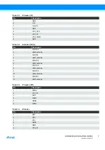
Table 3-1.
Headers Overview
Header
Designator
Description
J1
J1 (1x2) multiplexes PC5 and PC4 ports of the Atmel ATtiny1634 MCU between LEDs and XTAL pins.
J2
J2 (1x2) connects the Atmel ATtiny1634 VCC_CPU power pin to the VCC_VREG voltage regulator
output. Please note that the VREG output of the Atmel ATA663254 is limited to 85mA.
J3
J3 (1x2) connects the VCC_IO power pin to the VCC_VREG voltage regulator output. Please note
that the VREG output of the Atmel ATA663254 is limited to 85mA. VCC_IO is the supply voltage for
the LEDs, the potentiometer and is available on several headers.
J4
J4 (1x2) can be used to enable the pull-up resistor needed for a LIN master node. The jumper on this
header should be removed when operating the board as a LIN slave node.
J5
J5 (1x8) connects ATABtiny1634A-V1 PCB to external power supply (VCC, LIN_VS), GND, LIN IO
pin, VCC_VREG, and external power supplies (VCC_MCU, VCC_IO).
J6
J6 (2x6) connects the Atmel ATtiny1634 IO ports to the D0-D5 LEDs.
J7
J7 (2x3) is used as the ISP header.
J8
J8 (2x3) provides access to the Atmel ATtiny1634 ports (PB1, PB2, PC3), AREF, VCC_IO, and GND
pins.
J9
J9 (2x6) connects the Atmel ATtiny1634 to the QTouch on-board sensors, i.e., three buttons or a
slider. Place 1x2 jumpers across to connect the on-board buttons or a slider.
J10
J10 (1x2) connects the NRES of the Atmel ATA663254 LIN SBC to the NRES of the ATtiny1634 MCU.
J11
J11 (1x2) connects the external power supply on X2 to LIN_VS.
J12
J12 (1x2) is the autobaud enable header. It can be used to connect RXD1 to IC1 (Timer1/Counter1) to
measure sync bytes on RXD1.
J13
J13 (1x3) provides QTouch debug mode digital outputs.
J14
J14 (1x2) is a potentiometer enable header. Connects the potentiometer output to PB0 using a
jumper.
J15
J15 (2x6) multiplexes between QTouch sensors. Selects either three buttons (CS2, CS3, CS4) or one
slider (CS1).
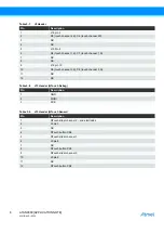
Table 3-2.
J1 Header (XTAL/LED)
Pin
Description
1
LED3
2
LED2
3
PC5
4
PC6
5
External crystal pin 1
6
External crystal pin 3

