


7
III
.
INSTALLATION STEPS
A. Location of installation
Check and ensure the installation location (concrete, layout, space size etc.) is
suitable for lift installation.
B. Use a carpenter’s
chalk line to establish installation layout of columns (See Fig.
7).
C. Check the parts before assembly.
1. Packaged lift and hydraulic power unit
(
See Fig. 8).
2. Move the lift aside with a forklift or hoist, and open the outer packing carefully and
move aside the top connecting assy. and parts box
(See Fig.
9
).
Shipment Parts list
Outer column
Parts box
Fig. 8
Fig. 9
Chalk Line
139 ½”
Fig. 7
Содержание Atlas PV-10HPX
Страница 1: ...1 Model PV10PX Revised 05 25 2021 ...
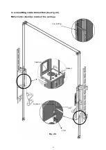
Страница 10: ...10 D Install parts of extension columns See Fig 16 Fig 16 24 26 20 42 25 37 41 ...
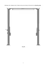
Страница 18: ...18 K Raise the carriages up by hand so they are locked at the same level See Fig 26 Fig 26 ...
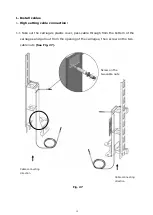
Страница 20: ...20 1 2 Connecting cable for high setting See Fig 28 Cable 1 Cable 2 Cable 1 High setting Fig 28 ...
Страница 22: ...22 Install power unit See Fig 30 Fig 30 ...
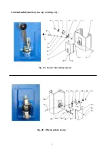
Страница 30: ...30 IV EXPLODED VIEW Model 211SAC Fig 43 ...
Страница 38: ...38 4 5 POWER UNIT EXPLODED VIEW 220V 60Hz Single Phase Fig 48 ...


