1
PAGE
Repair Instructions No.178.06/97
PN 6000 S
Special Tools
Required
■
Torx screwdriverTX 15
4931 599 004
■
Torx screwdriver TX 20
4931 599 005
■
Torx screwdriverbit TX 30
4932 319 998
■
Permanent-magnet holder
4932 315 508
■
Forcing disks
4931 599 021
■
(Dis-)Assembly tool
4931 599 011
Important!
■
Before beginning the maintenance work, perform an initial check with a high voltage test according
to VDE (see chapter Electrical and Mechanical Test Instructions).
■
Before all repair work, pull the power plug from the socket!
Disassembly
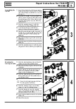
Detaching the
holding grip
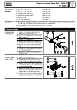
1
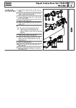
Remove the depth gauge (2) with the
holding device (3) from the tool.
2
Remove the holding device (3) from the
depth gauge (2).
3
Remove the holding grip (1).
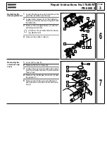
4
Remove the locking ring (9) with aid of
special pliers and remove the O-ring (8).
5
Remove the plastic holder (7) from the
tool.
6
Remove the pin (4) and the nut (6) from
the clamping plate (5).
7
Slightly bend up the clamping plate (5)
and push it off.
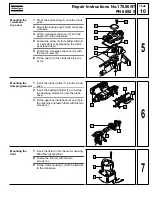
Detaching the
switch knob
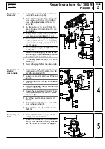
1
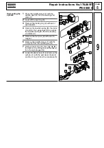
Remove the four screws (6).
2
Carefully lever off the gear box insula-
tion (3) at the edge using a screwdriver.
3
Remove the O-ring (5) from the gear box
insulation (3). Remove the locking ring (4)
with aid of special pliers.
4
Lever off the switch knob (9) from the out-
side and remove it together with the pres-
sure spring (1) as well as the ball (2).
5
Remove the shift pin (7) and the torsion
spring (8) from the gear box insulation (3).
1
6
5
4
3
2
7
8
9
1
1
6
5
4
3
2
7
8
9
2
Содержание PN 6000 S
Страница 1: ......

