6
PAGE
Repair Instructions No.178.06/97
PN 6000 S
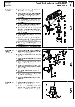
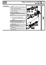
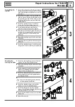
Dismantling the
reduction gear
1
Loosen the two screws (K) and pull the in-
dexing sleeve (H) completely from the
crankcase (6).
2
Remove the bearing (J) and the indexing
sleeve (H).
3
Press down the bevel gear (4) with aid of
the disassembly tool (service tool).
4
Keep it depressed and remove the locking
ring (5) with aid of special pliers.
5
Remove the bevel gear (4), the ball bear-
ings (3 and F), the needle bearings (7
and 2), the coupling (1), the backing
flange (8), the pressure spring (9), the
coupling sleeve (A), the coupling (B), the
balls (C), the indexing sleeve (D) as well
as the pinion (G) from the reduction gear
shaft (E).
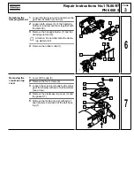
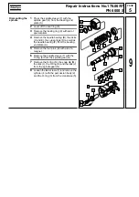
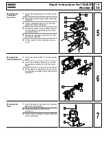
Dismantling the
crank assembly
1
Turn the crank gear (3) until the piston (5)
is located in the back dead centre.
2
Slightly lift the connecting rod (7).
3
Turn the crank gear (3) until it can be re-
moved from the crankcase (1). Remove it
together with the connecting rod (7), com-
pletely with piston (5) and O-ring (4).
☞
Do not apply any force! Do not jam the
piston (5) and the connecting rod.
4
Pull out the needle bearing (2) with aid of
an interior extractor.
5
Press the pin (6) from the piston (5) and
remove the piston (5).
6
Push the needle bearing (8) from the con-
necting rod (7).
D
1
6
5
4
3
2
7
8
9
A
B
C
E
G
H
F
J
K
10
2
3
4
5
6
1
7
8
11
Содержание PN 6000 S
Страница 1: ......

