8
PAGE
Repair Instructions No.178.06/97
PN 6000 S
Assembly
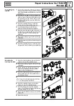
Assembling the
crank assembly
1
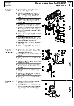
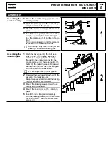
Mount the needle bearing (8) in the con-
necting rod (7).
2
Push the piston (5) over the connecting
rod (7) and mount the pin (6).
3
Press the needle bearing (2) into the crank
gear.
4
Insert the crank gear (3), the connecting
rod (7), the piston (5) and the O-ring (4)
into the crankcase (1). Mind the right posi-
tion!
Turn the crank gear (3) until the piston (5)
is located in the back dead centre.
☞
Do not apply any force! Do not jam the
piston (5) and the connecting rod.
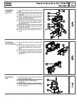
Assembling the
reduction gear
1
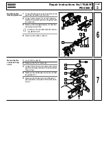
Push the bevel gear (4), the ball bear-
ings (3 and F), the needle bearings (7
and 2), the coupling (1), the backing
flange (8), the pressure spring (9), the
coupling sleeve (A), the coupling (B), the
balls (C), the indexing sleeve (D) as well
as the pinion (G) over the reduction gear
shaft (E) as shown in illustration.
☞
Fix the single balls (C) with grease.
2
Depress the bevel gear (4) with aid of the
assembly tool (service tool).
Keep it depressed and mount the locking
ring (5) with aid of special pliers.
3
Mount the indexing sleeve (H) with the
boring facing downward.
4
Mount the bearing (J) on the reduction
gear.
5
Insert the reduction gear completely
with the indexing sleeve (H) into the crank-
case and fasten it with the two secured
screws (K).
2
3
4
5
6
1
7
8
1
D
1
6
5
4
3
2
7
8
9
A
B
C
E
G
H
F
J
K
2
Содержание PN 6000 S
Страница 1: ......

