2920 1257 04
39
Instruction book
5.5 Adjustment MDR5/6 pressure switch
(Figs. 5.6 and 5.7)
Caution
-
Adjust the air pressure switch while it is pressurized.
-
Switch off the voltage before removing the cover of the
switch; reinstall it after an adjustment has been made and
before the voltage is switched on again.
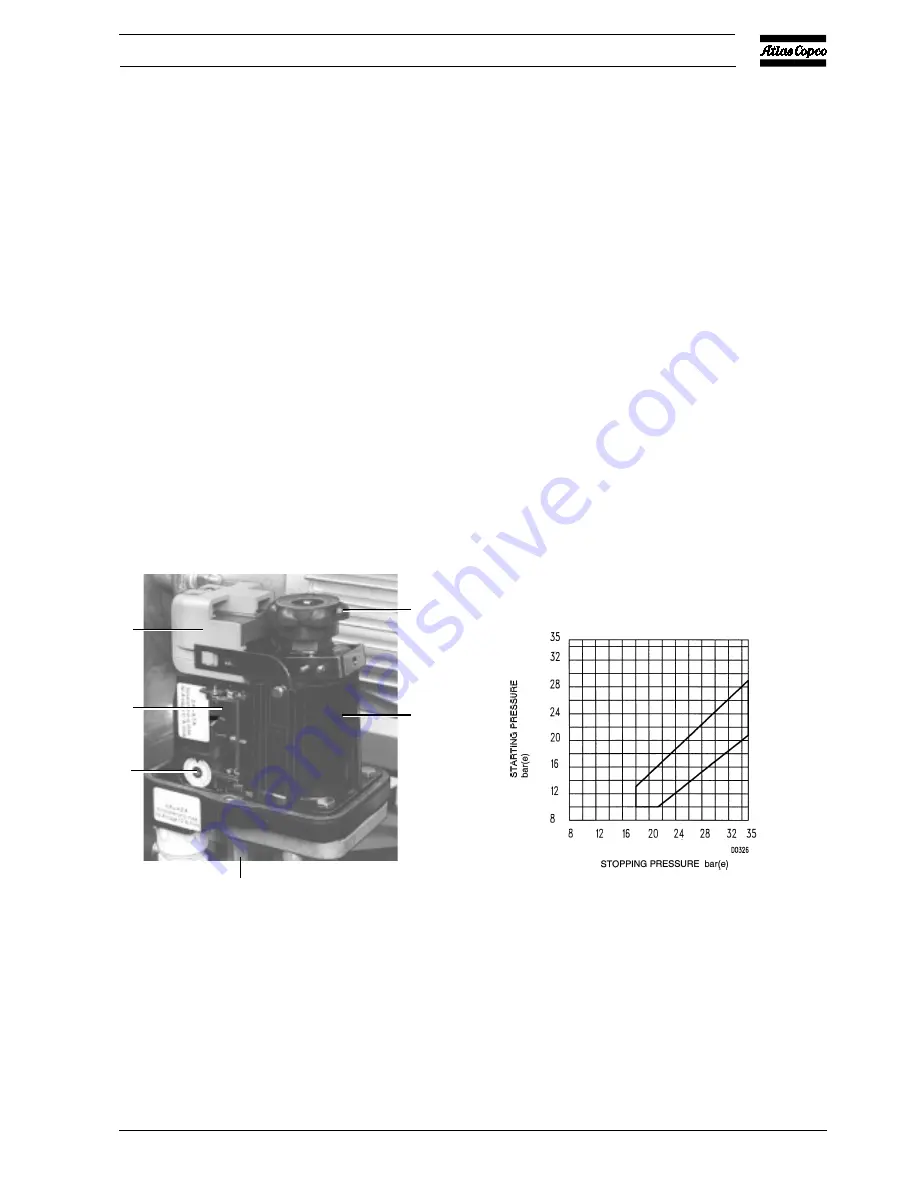
The maximum (stopping) pressure is controlled by adjusting
knob (1).
Turn the knob clockwise to raise the maximum or stopping
pressure, anti-clockwise to lower it.
The pressure difference is adjusted by means of the same
knob.
Push down the knob and turn it clockwise to reduce the
difference between the stopping and starting pressures, i.e. to
increase the starting pressure. Turn the knob anti-clockwise
to increase the pressure difference. The adjustment range is
shown on the diagram (Fig. 5.7).
5.6 Adjustment pilot valve on Trolley
(Fig. 5.8)
The adjustment of the maximum or unloading pressure of the
compressor is effected by means of pilot valve (RV-Fig. 1.16).
The valve also controls the difference between the preset
maximum pressure and that at which compression is resumed.
Unload mechanism
The pilot valve is equipped with a hand-operated unload
mechanism: by turning the red handle (1) 90 degrees, the
plunger of the valve will be lifted, releasing the spring force.
The air pressure from the pulsation dampers will force down
unloader plunger (12-Fig. 1.12), the compressor will run
unloaded. By turning handle (1) 90 degrees further, the plunger
returns to its original position so that the pilot valve will again
unload and load the compressor at the pre-set pressures.
1
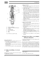
Adjusting knob for stopping and starting pressures
2
Spring housing, air pressure switch
3
Pressure release valve
4
Setting dial, overload relay
5
Motor overload relay
6
Switching mechanism
Fig. 5.6 View of pressure switch MDR5/6
Example: LT
Stopping pressure: 28 bar(e)
Starting pressure: adjustable between 15.5 and 22 bar(e)
Fig. 5.7
Pressure difference diagram, switch MDR5/35
(30 bar units)
Figs. 5.6 and 5.7 Air pressure switch MDR5/6 with ON/OFF switch (30 bar units)
6
5
4
3
50974F
2
1
Содержание LE110
Страница 11: ...2920 1257 04 11 Instruction book Fig 2 2 Dimension drawing LE LT55 75 and LF40 55 Power Pack ...
Страница 13: ...2920 1257 04 13 Instruction book Fig 2 4 Dimension drawing LT15 up to 40 Complete Unit vertical 250 l receiver ...
Страница 14: ...2920 1257 04 14 Instruction book Fig 2 5 Dimension drawing LE LT40 Complete Unit horizontal 250 475 l receiver ...
Страница 18: ...2920 1257 04 18 Instruction book Fig 2 9 Dimension drawing LE LF LT Pack with optional silencing hood ...
Страница 19: ...2920 1257 04 19 Instruction book Fig 2 10 Dimension drawing LE LT15 up to 40 Unsilenced Pack ...
Страница 20: ...2920 1257 04 20 Instruction book Fig 2 11 Dimension drawing LE LT55 75 and LF40 55 Unsilenced Pack ...
Страница 21: ...2920 1257 04 21 Instruction book Fig 2 12 Dimension drawing LE LT15 up to 150 with CD dryer ...
Страница 22: ...2920 1257 04 22 Instruction book Fig 2 13 Dimension drawing LE LF LT Trolley with electrical motor ...
Страница 23: ...2920 1257 04 23 Instruction book Fig 2 14 Dimension drawing LE LT75 up to 150 and LF75 Power Pack ...


