2920 1257 04
33
Instruction book
Warning
Never move the compressor after plugging in.
5. On compressors with DOL starter, push the (I) button
on top of the pressure switch.
On compressors with Y-D starter, push switch (S1-Fig.
2.21) to position (I)
6. Open the outlet valves.
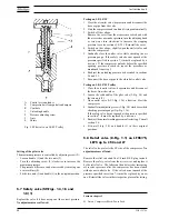
7. Set pilot valve (RV-Fig. 1.12) in the load position by
turning the red handle 90 degrees (see section 5.6).
8. Turn the regulating knob of the pressure regulator (14-
Fig. 1.12) clockwise or anti-clockwise to increase or
decrease the pressure at the outlet of the pressure regulator.
9. Regularly drain condensate (Dm-Fig. 1.15).
LE/LF/LT Trolley with petrol engine
1. On LE/LT, check the oil level, which must be near the top
of the red circle of sight-glass (SG-Fig. 1.3). The minimum
level is the lower part of the red circle.
2. Check the engine oil level as follows:
-
Remove the oil filler cap and wipe the dipstick clean.
-
Insert the dipstick into the filler neck, but do not screw
it in.
-
The oil level must show between the minimum and
maximum mark on the dipstick.
3. Fill the fuel tank with unleaded or low-leaded petrol
(gasoline).
4. Start the engine, consult the engine "Owner's manual".
5. Attach the air lines to the air outlets.
6. Open the outlet valves (AV1/2-Figs. 1.12 and 1.16).
7. Set pilot valve (RV-Fig. 1.12) in the load position by
turning the red handle 90 degrees (see section 5.6).
8. Turn the regulating knob of the pressure regulator (14-
Fig. 1.12) clockwise or anti-clockwise to increase or
decrease the pressure at the outlet of the pressure regulator.
9. Regularly drain condensate (Dm-Fig. 1.16).
3.3 Stopping
LE/LF/LT
1. On compressors with DOL starter, push the (0) button
on top of the pressure switch.
On compressors with Y-D starter, push switch (S1-Fig.
2.21) to position (0)
2. Close air outlet valve (AV-Figs. 1.4/1.6).
3. Switch off the voltage.
If a compressor with pressure switch with pressure release
valve stops during operation through a power failure, the
pressure from the air receiver must be released by pushing the
(0) button on top of the air pressure switch to prevent the
compressor from restarting against back-pressure when the
power becomes live again.
LE/LF/LT Trolley
1. Set pilot valve (RV-Fig. 1.12) in the unload position by
turning the red handle 90 degrees (see section 5.6).
2. On LE/LF/LT Trolley with electrical motor:
On compressors with DOL starter, push the (0) button
on top of the pressure switch.
On compressors with Y-D starter, push switch (S1-Fig.
2.21) to position (0).
If the compressor is not required for immediate further
use, switch off the voltage at the main circuit breaker and
unplug.
3. On LE/LF/LT Trolley with petrol engine:
Stop the engine, consult the engine "Owner's manual".
4. Close the air outlet valves (AV1/2-Fig. 1.12 and 1.16).
Depressurize and disconnect the air lines from the outlet
valves.
3.4 Taking out of operation at end of
compressor service life
At the end of the service life of the compressor, proceed as
follows:
1. Stop the compressor and close the air outlet valve(s).
2. Switch off the voltage and disconnect the compressor from
the mains.
3. Depressurize the compressor.
4. Shut off and depressurize the part of the air net which is
connected to the outlet valve. Disconnect the compressor
from the air net.
5. On LE/LT, drain the oil.
Содержание LE110
Страница 11: ...2920 1257 04 11 Instruction book Fig 2 2 Dimension drawing LE LT55 75 and LF40 55 Power Pack ...
Страница 13: ...2920 1257 04 13 Instruction book Fig 2 4 Dimension drawing LT15 up to 40 Complete Unit vertical 250 l receiver ...
Страница 14: ...2920 1257 04 14 Instruction book Fig 2 5 Dimension drawing LE LT40 Complete Unit horizontal 250 475 l receiver ...
Страница 18: ...2920 1257 04 18 Instruction book Fig 2 9 Dimension drawing LE LF LT Pack with optional silencing hood ...
Страница 19: ...2920 1257 04 19 Instruction book Fig 2 10 Dimension drawing LE LT15 up to 40 Unsilenced Pack ...
Страница 20: ...2920 1257 04 20 Instruction book Fig 2 11 Dimension drawing LE LT55 75 and LF40 55 Unsilenced Pack ...
Страница 21: ...2920 1257 04 21 Instruction book Fig 2 12 Dimension drawing LE LT15 up to 150 with CD dryer ...
Страница 22: ...2920 1257 04 22 Instruction book Fig 2 13 Dimension drawing LE LF LT Trolley with electrical motor ...
Страница 23: ...2920 1257 04 23 Instruction book Fig 2 14 Dimension drawing LE LT75 up to 150 and LF75 Power Pack ...


