2920 1257 04
36
Instruction book
5 Servicing and adjustment
procedures
Warning
Release the pressure from the compressor before
starting repair or maintenance works. Switch
off the voltage and isolate the compressor from
the mains.
5.1 Unloader or check valve
Dirt, condensate, coke formation and oxidation influence the
proper operation of the valve. Depending on the working
conditions (ambient temperature, working pressure, load cycle,
oil type), it is recommended to replace the unloader or check
valve as indicated in section 4.2. Replacement instructions
are included in the maintenance kits.
5.2 Valves
A faulty valve must be replaced immediately. A faulty valve
can be discovered as stated in section 6, points 1 and 4. It is
highly recommended to replace the valve discs, O-rings and
joints when the cylinder heads are disassembled.
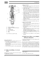
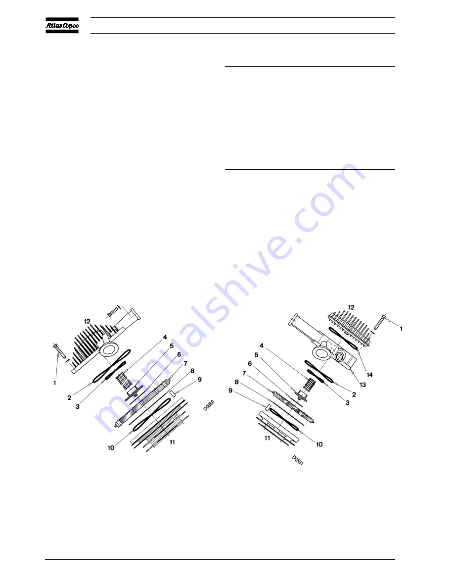
Replacement of valve discs (Figs. 5.1 and 5.2)
LE15/55
LE75 60 Hz Operation sequence
LE75 50 Hz HP cylinder
LF15/40
LE110/150
LE75 60 Hz HP cylinder
LP cylinder LT15/110
LE110/150
HP cylinder
LP cylinder LF55/75
LT15/110
HP cylinder
LP cylinder
LF55/75
LP cylinder
•
•
Remove the fan guard, unscrew
the cap and remove the cover (1-
Fig. 1.1), air filter and cover of
the air inlet silencer.
•
Disconnect cylinder head cover
(12) from the inlet and outlet pipe
flanges. Remove cover (12).
•
Disconnect head (13) from the
inlet and outlet pipe flanges.
Remove cylinder head cover
(12). Remove head (13).
Fig. 5.1
LE, LF15 up to -40 and low-pressure side of LT
and LF55
Fig. 5.2 High-pressure side of LT and LF55
1
Bolt
2
Joint
3
O-ring
4
Spring
5
Outlet valve guard
6
Outlet valve disc
7
Valve seat
8
Inlet valve disc
9
Guide pin
10
Joint
11
Cylinder
12
Cylinder cover
13
Cylinder head
14
Joint
Figs. 5.1 and 5.2 Cylinder heads
Содержание LE110
Страница 11: ...2920 1257 04 11 Instruction book Fig 2 2 Dimension drawing LE LT55 75 and LF40 55 Power Pack ...
Страница 13: ...2920 1257 04 13 Instruction book Fig 2 4 Dimension drawing LT15 up to 40 Complete Unit vertical 250 l receiver ...
Страница 14: ...2920 1257 04 14 Instruction book Fig 2 5 Dimension drawing LE LT40 Complete Unit horizontal 250 475 l receiver ...
Страница 18: ...2920 1257 04 18 Instruction book Fig 2 9 Dimension drawing LE LF LT Pack with optional silencing hood ...
Страница 19: ...2920 1257 04 19 Instruction book Fig 2 10 Dimension drawing LE LT15 up to 40 Unsilenced Pack ...
Страница 20: ...2920 1257 04 20 Instruction book Fig 2 11 Dimension drawing LE LT55 75 and LF40 55 Unsilenced Pack ...
Страница 21: ...2920 1257 04 21 Instruction book Fig 2 12 Dimension drawing LE LT15 up to 150 with CD dryer ...
Страница 22: ...2920 1257 04 22 Instruction book Fig 2 13 Dimension drawing LE LF LT Trolley with electrical motor ...
Страница 23: ...2920 1257 04 23 Instruction book Fig 2 14 Dimension drawing LE LT75 up to 150 and LF75 Power Pack ...


