Manual, Tool Changer, QC‑113
Document #9620‑20‑B‑113 Base Tool Changer‑05
Pinnacle Park • 1031 Goodworth Drive • Apex, NC 27539 • Tel: 919.772.0115 • Fax: 919.772.8259 •
www.ati‑ia.com
B-28
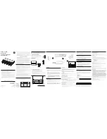
Figure 5.5— RTL Sensor Replacement (R2 Sensor)
(2) Cable Retaining Tabs
M3 Socket Head Cap Screws
M6 Socket Head
Cap Screws
Remove Module from Flat D
Connects
to "R2"
RTL Flat Pack
Style Sensor
Valve Adapter/Control Module
M3 Socket Head Cap Screw
8.
Unscrew the RTL sensor cable connector from the Valve Adapter/Control Module.
9. Remove the RTL sensor from the cable channel of the Tool Changer body. Discard the
removed RTL sensor.
10. Install the new RTL sensor, routing the cable into the cable channel of the Tool Changer body.
11. Attach the RTL sensor cable to the R2 connector on the Valve Adapter/Control Module.
12. Install the RTL sensor to the Tool Changer body.
13.
Apply Loctite 222
®
to the M3 socket flat head screw. Secure the sensor to the Tool Changer
body using a 2 mm hex key. Tighten to 60 in-ozs (0.4 Nm).
14. Install the (2) cable retaining tabs on Flat D of the Tool Changer body and secure with the (2)
M3 socket flat head cap screws using a 2 mm hex key. Tighten to contact.
15. If optional module was removed from Flat D, install the module.
16. Apply Loctite 242
®
to the M6 socket head cap screws fasteners.
17. Install the (2) (2) M6 socket head cap screws securing the module to the Tool Changer body
using a 5 mm hex key. Tighten to 40–70 in-lbs (4.5–7.9 Nm).
18. Confirm the operation of the RTL sensor by bringing a metallic object into close proximity to
the face of the sensor and watching for the LED in the body of the sensor to light up.


