background image

Modular Matrix Solution User Manual

54

Save to a Profile

The VM1600 allows you to store up to 32 (P1–P32) different connection 
profiles that can be saved and recalled later. When profiles are saved, they are 
saved according to the current connection configuration on the Main Screen. 
When you load a profile, the change is immediate and the profile number is 
shown in the lower right corner of the LCD display. To save profiles, from the 
Main Screen do the following:

1. Use the 

Menu

 pushbutton to access the Menu page, and 

Down

 to navigate 

to the next page. Press pushbutton 

1

 to open the Save to a Profile page.

2. To save the active connection configuration as a profile use the front panel 

number pushbuttons to select a profile into which you want to save the 
configuration.

Input ports 

1–16

 correspond to Profile 

P1 

to

 P16

Output ports 

1–16 

correspond to Profile 

P17 

to

 P32

3. Press the 

Profile 

pushbutton to store the connection configuration – the 

LCD shows a Profile Saved message.

4. Press 

Menu

 to return to the Menu page.

5. Press 

Cancel

 to return to the previous step without saving.

Note:

You can also access the Save to a Profile page by pressing the 

Profile 

pushbutton for longer than 3 seconds.

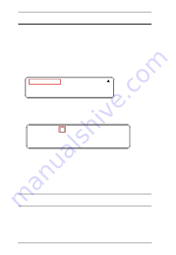
1:    Save to a Profile
2:    Play/Stop the Profile Schedule
3:    Turn Video Wall Off

Save to a Profile:   1
(In1->16 = P1->16; Out1->16 = P17->P32.
Press Profile to save.)

Содержание VM1600

Страница 1: ...t 3G SDI Input Board VM7404 4 Port HDBaseT Input Output Board VM7514 VM8514 4 Port HDMI Input Output Board VM7804 VM8804 4 Port DVI Input Output Board VM7604 VM8604 4 Port VGA Input Board VM7104 HDMI HDBaseT Lite Receiver with Scaler VE805R www aten com ...

Страница 2: ...will be required to correct the interference at his own expense The device complies with Part 15 of the FCC Rules Operation is subject to the following two conditions 1 this device may not cause harmful interference and 2 this device must accept any interference received including interference that may cause undesired operation FCC Caution Any changes or modifications not expressly approved by the...

Страница 3: ...ve defective following their purchase the buyer and not the manufacturer its distributor or its dealer assumes the entire cost of all necessary servicing repair and any incidental or consequential damages resulting from any defect in the software The manufacturer of this system is not responsible for any radio and or TV interference caused by unauthorized modifications to this device It is the res...

Страница 4: ...d 4 Terminal Block connectors 1 User Instructions VM7514 VM8514 The 4 Port HDBaseT Input Output Board package consists of 1 VM7514 4 Port HDBaseT Input Board 1 VM8514 4 Port HDBaseT Output Board 4 Terminal Block connectors 1 IR Transmitter 1 IR Receiver 1 User Instructions VM7804 VM8804 The 4 Port HDMI Input Output Board package consists of 1 VM7804 4 Port HDMI Input Board 1 VM8804 4 Port HDMI Out...

Страница 5: ...damaged in shipping If you encounter a problem contact your dealer Read this manual thoroughly and follow the installation and operation procedures carefully to prevent any damage to the unit and or any of the devices connected to it Features may have been added to the VM1600 VM7404 VM7514 VM8514 VM7804 VM8804 VM7604 VM8604 VM7104 VE805R since this manual was published Please visit our website to ...

Страница 6: ...804 iv VM7604 VM8604 iv VM7104 v VE805R v Contents vi About this Manual xi Conventions xii Product Information xii Chapter 1 Introduction Overview 1 Features 4 VM1600 4 VM7404 5 VM7514 VM8514 6 VM7804 VM8804 6 VM7604 VM8604 6 VM7104 7 VE805R 7 Requirements 9 Input Output Board 9 Source Devices 9 Display Devices 9 Cables 9 Browsers 10 Optional Equipment 11 Components 12 VM1600 Front View 12 VM1600 ...

Страница 7: ...able Connection 28 Installation Diagram 29 Chapter 3 Front Panel Operation Overview 31 Front Panel Pushbuttons 31 Basic Navigation 31 Front Panel LCD 32 LCD Password 32 Port Switching 33 Video Audio Pushbutton 33 Output Port Selection 36 Profile Pushbutton 38 LCD Menu 39 LCD Main Screen 40 IP Setting 41 Serial Port Setting 42 Serial Port Address Setting 42 Baud Rate 43 Serial Port Mode 43 Operatio...

Страница 8: ...iles 67 Digital Signage Profile 67 Grid View 69 Output Options 69 Video Wall Profile 70 Video Wall Options 70 Null Input 72 Independent Output 72 Grouping 73 Group 73 Display Preferences 74 Video Wall Example 1 74 Video Wall Example 2 75 Output Options 77 HDMI Audio Control 77 HDMI Video Options 79 System Settings 81 General 83 Serial Settings 83 Fan Status 83 Power Status 84 Device Info 84 Other ...

Страница 9: ...d output 107 9 SV Save the current connections into a profile 107 10 TI Set timeout 108 11 VR Software version information 108 Chapter 5 RS 232 Commands Serial Control Protocol Commands 109 RS232 Pin Assignment 109 Configuring the Serial Port 109 RS 422 RS 485 110 Verification 110 Switch Port Command 111 Mute Command 114 Volume Command 116 Save Load Profile Commands 118 EDID Mode Command 120 CEC C...

Страница 10: ...ution User Manual x International 138 North America 138 Specifications 139 VM1600 139 VM7404 140 VM7514 VM8514 141 VM7804 VM8804 142 VM7604 VM8604 143 VM7104 144 VE805R 145 VM PWR400 146 VM FAN60 146 Limited Warranty 146 ...

Страница 11: ...re for your Modular Matrix Solution installation Chapter 3 Front Panel Operation explains the fundamental concepts involved in operating the VM1600 at the local site via the front panel LCD display using pushbuttons Chapter 4 Browser Operation provides a complete description of the Modular Matrix Solution s web Graphical User Interface GUI and how to use it to remotely configure and operate the Mo...

Страница 12: ... key in Indicates keys you should press For example Enter means to press the Enter key If keys need to be chorded they appear together in the same bracket with a plus sign between them Ctrl Alt 1 Numbered lists represent procedures with sequential steps Bullet lists provide information but do not involve sequential steps Indicates selecting the option on a menu or dialog box for example that comes...

Страница 13: ...te analog stereo audio signals for independent routing The VM7514 VM8514 4 Port HDBaseT Input Output Boards offers an easy way to route any of 4 HDBaseT audio video sources to any of 4 HDBaseT display devices in combination with the ATEN Modular Matrix Switch When the VM8514 HDBaseT Output Board is used in conjunction with the VE805R HDBaseT Extender it features Seamless Switch technology and vide...

Страница 14: ...tion can be conveniently customized allowing users to independently switch and route video and or audio signals to various monitors displays projectors and or speakers simply by pressing front panel pushbuttons The VM1600 s built in Scaler encodes video formats in order to provide seamless real time switching while ensuring stable signal transmission In addition the front panel LCD shows a quick v...

Страница 15: ...end controller or PC The ATEN Modular Matrix Solution Series is a powerful integrated A V setup targeted towards broadcasting stations traffic and transportation related control rooms emergency service centers and any application that requires customizable high speed A V signal routing ...

Страница 16: ... TMDS high data transfer rate at 1080p 1920 x 1200 60Hz Control via front panel pushbuttons RS 232 RS 485 RS 422 serial ports and Ethernet connection Easy configuration via web browser Graphical User Interface GUI plus Telnet Built in bi directional RS 232 serial remote port for high end system control Hot pluggable Modular Fan Power Module Easy integration I O Boards Optional redundant power supp...

Страница 17: ...o audio output ports Supported SDI formats SD SDI SMPTE 259M up to 270Mbps HD SDI SMPTE 292M 296M up to 1 485Gbps 3G SDI SMPTE 424M 425M level A B DL up to 2 97Gbps Extensive input cable equalization distance 3G SDI in 100m HD SDI in 150m SD SDI in 300m Supports high resolution video SD Format Support PAL 50 PAL and NTSC 59 94 HD Format Support 1080p 23 98 24 25 29 97 30 50 59 94 60 1080PsF 25 29 ...

Страница 18: ...reams real time switching and stable signal transmissions Video Wall features configurable video wall profiles for custom layouts via point n click web GUI Bi directional IR channel for IR signal control IR transmission is processed one way at a time Supports full frequency IR signal from 30KHz to 60KHz VM7804 VM8804 4 HDMI input ports VM7804 4 HDMI output ports VM8804 Superior video quality HDTV ...

Страница 19: ...e activated VE805R HDBaseT Connectivity extends the connection between the VM8514 HDBaseT outputs and an HDMI display over a long distance via single Cat 5e 6 cable HDBaseT Anti jamming resists signal interference during high quality video transmissions using HDBaseT technology Bi directional RS 232 serial port for control and configuration Scaler features a scaling function to integrate a video w...

Страница 20: ...lar Matrix Solution User Manual 8 Note If Seamless Switch is enabled the video output will not display 3D Deep Color or interlace i e 1080i resolutions To use these features you must disable Seamless Switch ...

Страница 21: ...source device with HDMI output connector s For VM7804 4 port HDMI input board Digital A V source device with HDMI output connector s For VM7604 4 Port DVI input board Digital A V source device with DVI output connector s For VM7104 4 Port VGA input board A V source device with VGA output connector s Display Devices For VM8514 4 port HDBaseT output board VE805R HDBaseT Receiver Digital Display devi...

Страница 22: ...IR cable for each IR transmitter device VM7514 or VM8514 1 IR cable for each IR receiver device VM7514 or VM8514 Note No cables are included in this package We strongly recommend that you purchase high quality cables of appropriate length since this will affect the quality of the audio and video display Contact your dealer to purchase the correct cable sets Browsers Supported web browsers are show...

Страница 23: ...1 8 0_25 Firefox 33 Mac 10 10 V1 8 0_25 Safari 8 Model No Description Dimensions L x W x H Weight 2X 026G Easy Installation Rack Mount Kit Short 42 70 cm depth 2X 027G Easy Installation Rack Mount Kit Long 68 105 cm depth 2X 030G Left Video Wall TV Mounting Brackets 15 47 x 11 83 x 43 00 cm 2 00 kg 2X 030G Right Video Wall TV Mounting Brackets 15 47 x 12 80 x 43 00 cm 2 00 kg 2X RC1600 Video Wall ...

Страница 24: ...tons to use each function See Front Panel Pushbuttons page 31 for details Note The pushbuttons have LEDs that light to indicate they have been selected 3 Input Pushbuttons 1 16 These pushbuttons refer to the Input ports on the VM1600 rear panel Press to select the Input port These pushbuttons may also correspond to menu options profiles and other selections 4 Output Pushbuttons 1 16 These pushbutt...

Страница 25: ...odule is plugged in and working 7 Primary Power LED This LED lights green to indicate the primary power module is plugged in and working 8 Handles The two front handles are used to install the unit into a rack 9 Recessed Handles The two side handles are used to transport the unit No Component Description ...

Страница 26: ... the network The cable that connects the VM1600 to your LAN plugs in here See Cable Connection page 28 for further details 5 RS 485 RS 422 Serial Port Connect a computer or high end system controller via this serial port 6 Redundant Power Slot Optional This slot with protective cover is used to install an additional power supply for redundant power protection Note The extra power module is not inc...

Страница 27: ...s Unscrew the cover to insert the output boards into these 4 horizontal slots The display devices connect to the inserted Output boards 10 Fan Module This slot contains the fan module The fan is hot pluggable and the panel unscrews to install a replacement module See Depending on any optional equipment that you may have purchased one of the following may be included in your package Contact your AT...

Страница 28: ...PAL 50 PAL and NTSC 59 94 720p 25 29 97 30 50 59 94 60 1080i 50 59 94 60 1080PsF 25 29 97 30 1080p 23 98 24 25 29 97 30 50 59 94 60 No Component Description 1 SDI Input Ports Connect the cables from your video source devices to these ports 2 Analog Stereo Audio Input Ports Connect the cables from your audio source devices to these ports 3 Status LED The VM7404 has an LED to indicate the working st...

Страница 29: ...onnect the cables from your RS 232 device to the RS 232 ports 3 Status LED The VM7514 has an LED to indicate the working status No Component Description 1 HDBaseT Output Ports Connect the Cat 5e cables from your HDBaseT receiver to these ports 2 IR RS 232 Output Ports Connect the cables from your IR receiver to the mini stereo jack ports and connect the cables from your RS 232 device to the RS 232...

Страница 30: ...les from your audio source devices to these ports 3 Status LED The VM7804 has an LED to indicate the working status No Component Description 1 HDMI Output Ports Connect the cables from your HDMI display devices monitors projectors TVs to these ports 2 Audio Output Ports Connect the cables from your output audio devices or speakers to these ports 3 Status LED The VM8804 has an LED to indicate the w...

Страница 31: ...from your audio source devices to these ports 3 Status LED The VM7604 has an LED to indicate the working status No Component Description 1 DVI Output Ports Connect the cables from display devices monitors projectors TVs to these ports 2 Audio Output Ports Connect the cables from your output audio devices or speakers to these ports 3 Status LED The VM8604 has an LED to indicate the working status 1...

Страница 32: ...mponent Description 1 VGA Input Ports Connect the cables from your VGA video source devices to these ports 2 Audio Input Ports Connect the cables from your audio source devices to these ports 3 Status LED The VM7104 has an LED to indicate the working status 2 3 1 ...

Страница 33: ...805R and output board is established HDMI Out lights Orange to indicate the HDMI out put signal is good LED blinks Orange every second to indicate that the device is in F W upgrade mode 2 IRPort Connect the IR transmitter or receiver cable port into this mini stereo jack port 3 RS 232 Port Use the captive screw connectors 3 pole to connect the cable from your serial device into the RS 232 port 4 H...

Страница 34: ...or normal operation Set this switch to ON right and reset the unit s power to enter firmware upgrade mode see page 100 for details 6 HDBaseT Input Use a Cat 5e cable to connect the VE805R to the VM8514 output board 7 Power Jack The power adapter cable plugs connects here No Component Description ...

Страница 35: ...nt of the rack and align the holes of the unit s built in mounting brackets with the holes in the rack 2 Use screws to attach the unit to the rack 1 Important safety information regarding the placement of this device is provided on page 135 Please review it before proceeding 2 Make sure that the power to all devices connected to the installation are turned off You must unplug the power cords of an...

Страница 36: ...Note The Mounting Kit is not included with the package To purchase a mounting kit please contact your dealer 1 Screw the mounting brackets Easy Installation Rack Mount Kit see page 11 to the rack as shown in the diagram 2 Slide the unit along the brackets then screw the front panel to the rack Phillips I Head Phillips I Head M4L6 M4L6 ...

Страница 37: ... to ground the installation using the VM1600 s rear panel by connecting one end of the wire to the grounding terminal and the other end of the wire to a suitable grounded object 2 Make sure that all devices in your installation are properly grounded Note The grounding wire is not included in the package Please contact your dealer for details of purchase ...

Страница 38: ...e VM1600 do the following Note The four top slots on the Modular Matrix Switch are for the Input boards The four bottom slots on the Modular Matrix Switch are for the Output boards 1 On the rear of the VM1600 unscrew the two screws from a top and bottom slot and remove the covers Continues on next page ...

Страница 39: ... into a top slot and tighten the screws to secure the board to the VM1600 3 Slide an output board into a bottom slot and tighten the screws to secure the board to the VM1600 4 Repeat steps 2 and 3 to install additional I O boards 5 Power on the VM1600 ...

Страница 40: ...600 5 Connect your speakers audio output device s to the Audio port s of the Output Board on the VM1600 6 Optional If using the remote operation features web GUI plug a Cat 5e cable from the network into the VM1600 s Ethernet port 7 Optional If you are using a serial control function use an appropriate serial cable to connect the computer or serial controller to the VM1600 s female RS 232 serial p...

Страница 41: ...ardware Setup 29 Contact your ATEN dealer to purchase any of these additional accessories page 11 for details 11 Power on the VM1600 and all devices in the installation Installation Diagram 1 7 6 2 9 8 11 10 3 4 5 ...

Страница 42: ...Modular Matrix Solution User Manual 30 This Page Intentionally Left Blank ...

Страница 43: ...shbutton to configure the audio connections Use the MENU pushbutton to access the Menu page options IP Setting Serial Port Setting Operation Mode Security Mode and Save to a Profile Use the PROFILE pushbutton to select a profile or switch between the connection profiles which have been added to the Profile List see page 59 Pressing this pushbutton for longer than 3 seconds displays the Save to a P...

Страница 44: ...M1600 for the first time the default password is 1234 To enter a password do the following 1 Check that the cursor is flashing on the first digit 2 Use the front panel number pushbuttons 1 9 to enter a 4 digit password After the fourth digit the cursor goes back to the first digit 3 Press Cancel to clear the password The digits revert to 4 asterisks and the cursor returns to the first digit Note 1...

Страница 45: ...n to configure Video connections The built in LED lights up and the LCD displays Video on the lower right side Press the button again to cancel Press the Audio pushbutton to configure Audio connections The built in LED lights up and the LCD displays Audio on the lower right side Press the button again to cancel If both Video and Audio built in LEDs are turned off the video and audio channels are c...

Страница 46: ...put port do the following 1 Press any Input port pushbutton The Output port LED s tied to the said Input port will begin to flash Available Output port LED s will light up steady In the example below pressing Input port 1 shows it is tied to Output ports 1 and 2 Continues on next page INPUT OUTPUT 1 2 5 5 1 1 3 4 1 2 3 4 5 6 7 8 INPUT OUTPUT 1 2 5 5 1 1 3 4 9 10 11 12 13 14 15 16 V A P1 ...

Страница 47: ...bove press the Output port 2 pushbutton The Output port 2 LED will also begin to flash 0 5 sec on 0 2 sec off This indicates that Input port 2 is now connected to Output ports 2 3 and 4 Once the signal from the selected Input port is successfully tied to the Output port the LEDs turn off and the LCD information is updated Note 1 Pressing an Input port a second time deselects it 2 Input ports that ...

Страница 48: ... up Because no Input LEDs are flashing no ports have already been assigned to Output port 1 2 If an Output port pushbutton is pressed a second time it is deselected and the LED turns off 3 To connect the selected Output port s to an Input port press the Input port pushbutton to which you want the Output port s tied The newly selected Input port LED flashes 0 5 sec on 0 2 sec off and the LCD inform...

Страница 49: ...ied In the example below Input port 3 has been pressed and is now connected to Output ports 2 3 and 4 Note 1 Pressing an Output port a second time deselects it 2 Pressing the Cancel pushbutton once stops the Output Port Selection operation and the LCD displays the active setting Pressing the Cancel pushbutton again turns all LEDs off 3 After 10 seconds of inactivity all the LEDs turn off ...

Страница 50: ... configured in the Profile The selected Profile is shown as P1 P32 in the LCD s lower right corner Up and Down buttons correspond to the previous or next profile in the Profile List which can be edited via the GUI If there are no profiles configured an error message No Profile List defined Profile List can be edited via the Web GUI is displayed The Profile List and connections can be edited from t...

Страница 51: ...rtup check the front panel LCD to view the loading progress If the LCD Menu fails to load an error message displays Reset the unit and try again Menu Page Sub Menu Page s IP Setting IP Address Subnet Mask Gateway Serial Port Setting Baud Rate 9600 19200 38400 115200 Operation Mode EDID Default Port1 Remix Customized CEC On NA OSD On NA Output Status Video On NA Stereo Audio 01 16 Output Resolution...

Страница 52: ...e bottom half The front panel pushbutton label 1 16 corresponds to the Input ports and Output ports on the unit s rear panel Use the Menu pushbutton to go to the Menu page Use the Profile pushbutton to switch between profile connections see Profile List page 59 INPUT OUTPUT 1 2 5 5 1 1 3 4 1 2 3 4 5 6 7 8 INPUT OUTPUT 1 2 5 5 1 1 3 4 9 10 11 12 13 14 15 16 V A P1 ...

Страница 53: ...urity Mode page Press Down button to go to the next page Press Menu to return to the Menu Screen Press Cancel to return to the Main Screen 2 After pressing 1 the IP address Subnet Mask and Gateway information are shown The default IP address is 192 168 0 60 The default Subnet Mask is 255 255 255 0 The default Gateway is 192 168 0 1 3 Press Cancel to return to the previous step without change 1 IP ...

Страница 54: ...rom the Serial Port Setting submenu by pressing 1 2 Press pushbuttons 1 16 to make your selection Note The default serial port address is 1 This address is used for RS422 485 commands to control multiple VM1600 s 3 Press Menu to return to the Menu page 4 Press Cancel to return to the previous step without saving 1 IP Se ng 2 Serial Port Se ng 3 Opera on Mode 4 Security Mode 1 Serial Port Address S...

Страница 55: ...ote The default baud rate is 19200 3 Press Menu to return to the Menu page 4 Press Cancel to return to the previous step without saving Serial Port Mode 1 Select Serial Port Mode from the Serial Port Setting submenu by pressing 3 1 Serial Port Address Se ng 1 2 Baud Rate Se ng 19200 3 Serial Port Mode RS232 1 9600 2 19200 In use 3 38400 4 115200 1 Serial Port Address Se ng 1 2 Baud Rate Se ng 1920...

Страница 56: ...ttons 1 2 to make your selection Serial Port options are 1 RS 232 2 RS 422 RS 485 Note The default serial port mode is RS 232 3 Press Menu to return to the Menu page 4 Press Cancel to return to the previous step without saving 1 RS232 In use 2 RS422 RS485 ...

Страница 57: ... HDMI devices to communicate and respond to one remote control The OSD when enabled for a port displays real time port switching information on the screen The Output Status shows whether the video audio of an Output port is turned on or off EDID To adjust the EDID mode do the following 1 From the Operation page press pushbutton 1 to access the EDID Mode page 2 Press pushbuttons 1 4 to make your se...

Страница 58: ...wered on 2 Port1 EDID data read from port 1 is passed to all video sources The system will enforce the Default EDID setting if port 1 is not occupied 3 Remix This mode reads the EDID data from all connected displays and generates the optimum EDID for all video sources The system will not re generate a new EDID when a new device is plugged in unless triggered by a pushbutton or command 4 Customized...

Страница 59: ...e ON or disable NA the CEC feature for the output port If the port does not support CEC an NA is shown Note The default CEC setting is Off 3 Press Menu to return to the Menu page 4 Press Cancel to return to the previous step without saving 1 EDID Mode Default 2 CEC 3 OSD 4 Output Status OUTPUT 1 2 3 4 5 6 7 8 NA NA NA NA ON NA ON NA OUTPUT 9 10 11 12 13 14 15 16 ON ON ON ON NA NA NA NA ...

Страница 60: ...D setting for each output port do the following 1 From the Operation page press pushbutton 3 to access the OSD page 2 Press pushbuttons 1 16 to enable ON or disable NA the OSD feature for the port Note The default OSD setting is Off 3 Press Menu to return to the Menu page 4 Press Cancel to return to the previous step without saving 1 EDID Mode Default 2 CEC 3 OSD 4 Output Status OUTPUT 1 2 3 4 5 6...

Страница 61: ... disable NA the video channel Note The default Output Status setting is On 4 If configuring the output port status for stereo audio press pushbuttons 1 16 to select the output port Adjust the audio volume for the port by pressing the Up or Down pushbutton Note The audio volume range from 0 mute and 1 27dB to 10 0dB The default audio volume is 10 1 EDID Mode Default 2 CEC 3 OSD 4 Output Status 1 Vi...

Страница 62: ... 5 If configuring the output video resolution press pushbuttons 1 16 to select the output port Next select the preferred output resolution 6 Press Menu to return to the Menu page 7 Press Cancel to return to the previous step without saving ...

Страница 63: ...the Menu pushbutton to access the Menu page then press pushbutton 4 to access the Security Mode page Mode 1 To set the VM1600 so that it requires a password for local operation press pushbutton 1 in the Security Mode page 2 To disable security settings press pushbutton 1 3 To require a password after the LCD display times out or is powered off on press pushbutton 2 4 To enable a lock screen press ...

Страница 64: ...ld password see LCD Password page 32 If the old password is entered correctly you can proceed to the next step The default password is 1234 Note If you enter an incorrect password the cursor goes back to the first digit and reverts to flashing The Incorrect Password message clears as soon as a new digit is entered 3 In the New Password field the cursor flashes at the first digit Enter the new pass...

Страница 65: ...d does not match the one entered in the previous screen an error message appears Enter the new password correctly 5 Press Menu to return to the Menu page 6 Press Cancel to return to the previous step without saving Old Password New Password Re enter New Password ...

Страница 66: ...n 1 to open the Save to a Profile page 2 To save the active connection configuration as a profile use the front panel number pushbuttons to select a profile into which you want to save the configuration Input ports 1 16 correspond to Profile P1 to P16 Output ports 1 16 correspond to Profile P17 to P32 3 Press the Profile pushbutton to store the connection configuration the LCD shows a Profile Save...

Страница 67: ...edule Turn Video Wall Off If a video wall is currently playing a submenu will appear Selecting Turn Video Wall Off will return port assignments to their default i e disassemble the video wall 1 Save to a Profile 2 Play Stop the Profile Schedule 3 Turn Video Wall Off 1 Save to a Profile 2 Play Stop the Profile Schedule 3 Turn Video Wall Off ...

Страница 68: ...Modular Matrix Solution User Manual 56 This Page Intentionally Left Blank ...

Страница 69: ...ges and up to 32 users can log into the GUI at one time For full details see the sections that follow Logging In To access the GUI type the VM1600 s IP address into the address bar of any browser If a Security Alert dialog box appears accept the certificate it can be trusted The login screen appears The default IP address is http 192 168 0 60 The default Username and Password are administrator pas...

Страница 70: ...ure the input to output connections by creating profiles The page is divided into three parts the Menu Bar Profile List and Profile Scheduling Menu Bar The Menu Bar consists of the Settings icon and Logout button Click Settings to enter the System Settings see page 81 Click the Logout button to log out of the GUI ...

Страница 71: ...ly via the unit s front panel pushbuttons and via the web GUI Adding Playing a Profile To configure a new or existing connection profile 1 From the Profile List click an empty or existing Profile icon 2 For a new profile select the profile type Digital Signage Select this option for video that is displayed independently on separate monitors page 67 Video Wall Select this option for monitors that a...

Страница 72: ...gnage page 67 or Video Wall page 70 profile 4 Once you create a profile it appears in the Profile List as shown here 5 Select the profile and click Apply 6 The profile appears in the large Play window and the connections start Note More information about the Profile List is provided on the next page ...

Страница 73: ...e following 1 Click Export Profiles A configuration file will then begin downloading To import connection profiles to the VM1600 do the following 1 Click Import Profiles 2 Browse to the configuration file select it and click Open Note Importing a connection profile database will overwrite the current profiles ...

Страница 74: ...ng a Profile or the Play window opens a pop up menu with options Profile Option Description Apply Click Apply to put the profile in the Play window This allows you to start the profile connections Edit Click Edit to configure the profile s input to output connections ...

Страница 75: ...quence Click to advance to the next profile in the sequence when Profile Scheduling is in use Only available with On Sequence Positioning Click Positioning to open a window that allows you to adjust the image position on each display For Video Wall profiles you can also set the Bezel Dimension which is the frame thickness between each display Remove Removes the profile from the Play window Edit Cl...

Страница 76: ...on Description Show OSD Check Show OSD to show text updates that appear on the display when configuration or port changes are made Mute All Check Mute All to mute the audio for all ports Blank All Check Blank All to turn off the video to all displays ...

Страница 77: ... List Scheduling allows you to queue and play connection profiles in sequence for a specific amount of time Option Description Click to edit profile schedule Click to play profile schedule Click to stop profile schedule Click to change to next or previous profile when a profile schedule is playing ...

Страница 78: ...dule Use the drop down menu to select the duration Hours Minutes or Seconds and enter the amount of time for the profile to play After the time expires the schedule switches to the next profile Use Repeat to stop switching between schedules and stay on the currently selected profile If Repeat isn t used the schedule will loop back to the first profile If Repeat is used a specific number of hours m...

Страница 79: ...an output port and the connected display The large number is the Input port selected for the display The small number upper left corner is the Output port for the display Click the icons to select options Select icons to choose the Video Input from the Select Source menu Click the PEN icon or name to edit the profile name Click Select All to select all outputs Click Unselect All to unselect all ou...

Страница 80: ...n the video off on Option Description Select Source The Select Source menu appears when you click an Output icon Video Input Use the drop down menu to select the Video Input port Audio Input Use the drop down menu to select the Audio Input source Lock Unlock Lock the icon to set the same source for the Video Audio Input when one is changed the other changes to match it Unlock the icon to set diffe...

Страница 81: ...urn green yellow or red Uncheck an Output Port box to disable the video for that Output Port The column will turn dark grey Check an Output Port box to enable the video for that Output Port Click Test to play the current profile without saving Click Save Apply to save a profile and begin playing it Click Save to save the profile Click Save as to save the profile as a different profile number Click...

Страница 82: ...ge 74 Click multiple icons to Group Outputs see Grouping page 73 and choose the Video Input from the Display Preference menu Use next to Display Layout _1 to create additional layouts under the same profile Click the PEN icon or name to edit the profile name Click Select All to select all outputs Click Unselect All to unselect all outputs Click Test to play the current profile without saving Click...

Страница 83: ...the layout Output Order Automatically assign output ports by selecting one of the following options Left to right top to bottom right to left top to bottom top to bottom left to right or top to bottom right to left Bezel Dimension Use the four boxes to increase decrease the frame size for each active display Monitor Lock Unlock Click the monitor icon to Lock the 4 bezel settings so that when one s...

Страница 84: ...reen see Grouping page 73 You must first set the Output port for each icon Drop Down Menu Use the drop down menu to select the Output port Option Description Independent Independent Outputs are displays that have their own Video Input and Output selected Independent Outputs Display their own video Icons have their own color and Video Input Select an Independent Output and use the Display Preferenc...

Страница 85: ...or see page 73 Ungroup Select a group and click to ungroup the displays Option Description Group A Group of Outputs shares the same Video Input and displays the video together as one large screen A Group of Outputs Displays video across multiple monitors to form one screen Icons have the same color and Video Input number Select a Group and use the Display Preferences menu to select the Video Input...

Страница 86: ... appear here You can use the output icon s drop down menu to change the output port for the display Video Input Use the drop down menu to select the Video Input port Audio Input Use the drop down menu to select the Audio Input source Lock Unlock Lock the icon to set the same source for the Video and Audio Input when one is changed the other changes to match it Unlock the icon to set different sour...

Страница 87: ...te separate video walls see Video Wall Options page 70 Video Wall Example 2 The example below shows a video wall with 16 displays Each Group and Independent Output has a unique color This video wall has 3 Groups and 2 Independent displays The Blue Group will show Video Input 02 across six displays as one large screen The Brown Group will show Video Input 05 across six displays as one large screen ...

Страница 88: ...Modular Matrix Solution User Manual 76 The Orange and Purple Independent displays will show the video from their own Video Input 03 and 04 ...

Страница 89: ...ing to all ports All Ports Use HDMI Audio All Ports Use Stereo Audio uses the stereo audio port All Mute mutes all ports Port_ HDMI Stereo Use the drop down menu to apply audio settings to each port Use HDMI Audio port uses the HDMI audio Use Stereo Audio port uses the Stereo audio Mute mutes HDMI Stereo for the selected port Stereo Volume Use and to increase or decrease the audio level Click Test...

Страница 90: ... Solution User Manual 78 Click Save Apply to save a profile and begin playing it Click Save to save the profile Click Save as to save the profile as a different profile number Click Cancel to undo all unsaved changes ...

Страница 91: ...ition Allows you to fade the video display when the Input port is changed Use the period option to set the fade speed Use the drop down menu to apply options to all ports or On Off button to enable disable Transition per port Period Sets the fade speed for the Transition option Use the drop down menu to apply an option Slow Normal or Fast to all ports or lower drop down menus to apply options per ...

Страница 92: ...Modular Matrix Solution User Manual 80 Click Save to save the profile Click Save as to save the profile as a different profile number Click Cancel to undo all unsaved changes ...

Страница 93: ...an also view Temperature Fan and Power statuses and Slot Information The User Account page allows you to add and edit user accounts The Port Name page allows you to name each input and output port The Network page allows configuration of the network settings The EDID page is used to set the EDID modes The Maintenance page is for upgrading the device s firmware The IR RS232 Channel page allows you ...

Страница 94: ... Manual 82 The OSD CEC page allows users to control port OSD and CEC settings Click Profile List to return to the Main page Note The IR RS232 Channel page is only available when VM7514 VM8514 I O boards are installed in the VM1600 ...

Страница 95: ...Serial Port Mode drop down menu to select a signal for the serial port RS232 RS422 RS485 If you are using RS422 RS485 select the Serial Port Address Options are 1 16 Use the drop down menu to select the Baud Rate for the serial port Fan Status This section displays the internal temperature and status of the cooling fans Fans rotate to indicate they are working ...

Страница 96: ...nits Device Info This section lists the device and input output boards type Model Name Firmware Version Temperature and Power Consumption Other Use the Language drop down menu to select a preferred user interface language Options include English French German Italian Japanese Korean Portuguese Russian Spanish Simplified Chinese and Traditional Chinese Use the Baud Rate drop down menu to select a s...

Страница 97: ...add another user to the list The VM1600 supports up to 32 users at one time see page 85 for more details Edit Click the Edit button to change user information This option allows an Administrator to edit individual accounts Edit Rename the user account set the password add a description and set the user s permission level see page 87 for more details Delete Removes the user account The default user...

Страница 98: ...ord to confirm Note Usernames and passwords accept multi lingual characters and must be 5 16 alphanumeric characters excluding Passwords are case sensitive Usernames only support lower case letters Add or edit the description for the user Select the permission level that you want to grant the user see page 86 Click Create User to save the data Click Cancel to discard the changes and exit If a user...

Страница 99: ...n level The three available permission levels are as follows Administrator this level provides full access and control of the VM1600 in addition to full User Management privileges Advanced User this level provides full access and control with no User Management privileges Basic User this level only provides basic functions connections and open profiles ...

Страница 100: ...or easy identification To name an Input Output port enter a descriptive name of up to 16 characters including 0 9 a z A Z _ in the corresponding field To change an Input Output port s name enter another value and click Save Click Reset to clear all stored names Note The Input and Output port names can be the same ...

Страница 101: ...e Click Reset to use the following default values IP Address 192 168 0 60 Subnet Mask 255 255 255 0 Default Gateway 192 168 0 1 Website Timeout N A 5 10 30 60 minutes Telnet Configuration enabled checked Enter the values then click Save Changes may take a few seconds and after refreshing the page automatically redirects you to the IP address specified This option controls how long an inactive web ...

Страница 102: ...that the VM1600 can use the best resolution for its display s Note The EDID Mode can also be selected via the Front Panel pushbuttons see Operation Mode page 45 Extended Display Identification Data EDID is a data format that contains a display s basic information and is used to communicate with the video source system ...

Страница 103: ...uttons Select the EDID Mode to use and click Apply The VM1600 uses the settings configured for that EDID mode Options are ATEN Default All ports EDID are the same as the hardware default EDID Port 1 Mode All ports EDID are the same as Port1 s EDID Remix All ports EDID use the best display resolution Customized See Customized Mode see page 93 ...

Страница 104: ...option that you want to view and or edit There are two categories EDID Extended Display Identification Data and CEA Consumer Electronics Association When you highlight the menu items on the left column the right column displays the current settings for the corresponding EDID configuration Some of the screens are read only See EDID Settings page 90 for more information on these two columns ...

Страница 105: ...Apply Port EDID Status Select which input source port you want to store the EDID configuration 01 16 Retrieve EDID Click and a pop up window appears to retrieve the EDID settings of a stored EDID configuration Customized EDID 01 16 Display Port or ATEN Default Select the port to retrieve The right panel displays a summary of the acquired EDID settings that you can edit Click Save and select the co...

Страница 106: ...DID Modes Port 1 Default and Remix cannot be edited The pages for the Customized EDID which can be edited are discussed in the proceeding sections Established Timings This page lists video resolutions timings that display devices can support Select the resolution s you want to use for the attached monitor display device Click Clear All to deselect all the items Click Select All to check all the it...

Страница 107: ...ings page Select the H Active Pixel from the drop down menu Select the Aspect Ratio from the drop down menu Click Save to apply the changes Detail Timing Display Description This screen gives more video resolution options and provides resolution timing details In the drop down menu choose a resolution with values that fit the attached monitor display device and click Save ...

Страница 108: ... Description This screen lets you specify the viewing specifications namely horizontal and vertical scan ranges and pixel clock rate of your monitor display device Enter the values that correspond to your device and click Save to apply the changes ...

Страница 109: ... the EDID structure which further extends the standard definitions of EDID to support advanced features of monitors display devices Display Support This screen describes the display s basic digital components Select the YCbCr mode applicable to your display and click Save ...

Страница 110: ...ing displays that may be supported by other devices other than PC monitors for example 1080i Select the native resolution of the attached display device Select the resolutions that work with the attached monitor display device Click Clear All to deselect all the items Click Save to apply the changes ...

Страница 111: ...pplicable to your audio output device and click Save to apply the changes Detail Timing Display Description This screen gives more video resolution options and provides resolution timing details in addition to those specified in the EDID structure In the Resolution drop down menu choose a resolution with values that fit the attached monitor display device and click Save ...

Страница 112: ... cache and then close and reopen the web browser This will ensure the GUI refreshes and functions properly To back up the VM1600 s system settings do the following 1 Click Backup A configuration file will then begin downloading To restore the VM1600 s system settings do the following 1 Use the Browse button to locate the configuration file Make sure you have the correct file saved on your PC 2 Cli...

Страница 113: ...ware Upgrade switch to ON 4 Reset the VE805R s power to enter firmware upgrade mode The HDMI Out LED blinks orange every second to indicate the device is in F W upgrade mode 5 At this point you can run the firmware upgrade package from the computer connected to the VE805R ...

Страница 114: ...ion to control devices locally Loopback prevents the IR RS232 signals from being sent across the connection to another I O board The Loopback setting is good when you use a VM8514 board to extend displays but use a different board type not VM7514 for input devices and want to use the IR RS232 signals for local control In Board Set each input port to use the Local IR RS232 HDBaseT IR RS232 or Loopb...

Страница 115: ...et each output port to use the Local IR RS232 HDBaseT IR RS232 or Loopback setting for the IR RS232 signals Use the drop down menu to apply an option to all ports or select Local IR RS232 HDBaseT IR RS232 or Loopback for individual ports Click Save to save the settings Click Reset to revert to the default settings Note By default the RS232 Return Path will use the lowest port number available for ...

Страница 116: ...is HDCP 1 4 or non HDCP enabled either individually or by applying one setting to all ports Connection Here users can find a visual display of connection paths between inputs and outputs When selecting an input its path is displayed in green Output Here users can define whether or not HDCP settings are fixed either by individual port or by applying one setting to all ports By prearranging and fixi...

Страница 117: ...on and port changes are made to its output Use the drop down menu to apply options to all ports or ON OFF button to enable disable the OSD for each port CEC Consumer Electronics Control CEC allows interconnected HDMI devices to communicate and respond to one remote control Use the drop down menu to apply options to all ports or On Off button to enable disable CEC for a port Click Save to save the ...

Страница 118: ...user logs on using a Username that is already in session the newest login takes effect and the previous session is replaced Configuration Menu Once a Telnet connection to the VM1600 is established the device s text based Configuration Menu comes up with the following items 1 H Call up the command list for help Command list IP Set IP address LO Load connections from profile nn PW Change password RI...

Страница 119: ...Read what input is connected to nn output RI 01 Input port 02 04 08 is connected to output port 01 6 RO Read what output is connected to nn input RO 01 Output port 02 is connected to input port 01 7 SB Set serial port baud rate SB 96 Serial port baud rate is set to 9600 8 SS Switch input to specified output SS 01 03 Switch input 01 to output 03 00 Local Port 9 SV Save the current connections into ...

Страница 120: ...onnections into profile 01 10 TI Set timeout TI 30 Set 30 minute timeout 11 VR Software version information VR Software version 1 0 Note For further information about these functions please reference the equivalent Browser GUI functions earlier in this chapter ...

Страница 121: ... a high end controller or PC RS232 Pin Assignment Configuring the Serial Port The controller s serial port should be configured as follows Pin Description Pin Description 1 Not connected 6 Not connected 2 RXD 7 Not connected 3 TXD 8 Not connected 4 Not connected 9 Not connected 5 GND Baud Rate 19200 Data Bits 8 Parity None Stop Bits 1 Flow Control None ...

Страница 122: ...85 serial port devices when the VM1600 is setup in cascade installation Verification After entering a command a verification message appears at the end of the command line as follows Command OK indicates that the command is correct and successfully performed by the switch Command incorrect indicates that the command has the wrong format and or values ...

Страница 123: ...o turn off video output on port 03 type the following sw o03 off Enter 4 To turn off video output on port 03 on device 02 type the following sw o03 a02 off Enter The following tables show the possible values for the Switch Port command Command Description sw Switch command Input Description i Input port command Num1 Description xx Input port xx 01 16 All input ports Output Description o Output por...

Страница 124: ...dress for RS 232 commands Num3 Description zz Device address zz 01 16 default is 01 RS 422 and RS 485 only All devices Control Description on Turn on the display off Turn off the display Next Port Previous Port Command Input Input Port Output Output Port Address Device No Control Enter Description sw i xx o yy a zz Enter Switch Input Port xx to Output Port yy on address zz xx 01 16 yy 01 16 zz 01 ...

Страница 125: ...Chapter 5 RS 232 Commands 113 3 The Port Number and Address command strings can be skipped and the default value will be used ...

Страница 126: ...te o03 on Enter 2 To turn mute off on all output ports type the following mute o off Enter 3 To mute the audio for output port 09 on device 03 type the following mute o09 a03 on Enter The following tables show the possible values for the Mute command Command Description mute Mute command Output Description o Output port command Num1 Description xx Output port number xx 01 16 default is 01 All outp...

Страница 127: ... 232 commands 3 Skip the Output command to mute or enable the audio of all output ports The following table shows the available command list off Mute off audio on output port is enabled default Command Output Num1 Address Num2 Control Enter Description mute o xx a zz on Enter Mute audio for output port xx on device zz xx 01 16 zz 01 16 mute o xx a zz off Enter Turn mute off for output port xx on d...

Страница 128: ...04 type the following volume o v04 Enter 3 For example to adjust the volume for output port 06 on device 01 to level 14 type the following volume o06 a01 v14 Enter The following tables show the possible values for the Volume command Command Description volume Volume command Output Description o Output port command Num1 Description xx Output port xx 01 16 default is 01 All output ports Address Desc...

Страница 129: ...2 485 commands the default a00 will be used Skip the address for RS 232 commands The following table shows the available command list Control Description zz Audio volume level zz 01 10 default is 10 Command Out put Num1 Address Num2 Vol ume Control Enter Description volume o xx a yy v zz Enter Adjust volume for output port xx on device yy to level zz xx 01 16 yy 01 16 zz 01 16 ...

Страница 130: ...ad connection profile 04 type the following profile f04 load Enter 3 To save the current connection configuration of device 03 as profile 08 type the following profile f08 a03 save Enter The following tables show the possible values for commands Command Description profile Save Load Profile command Profile Description f Profile command Num1 Description xx Profile number xx 01 32 default is 01 Addr...

Страница 131: ... RS 232 commands 3 If the Address or Profile parameter is skipped the default value will be used The following table shows the available command list load Load a saved profile Command Profile Num1 Address Num2 Control Enter Description profile f xx a yy save Enter Save current connection configuration on device yy as profile xx xx 01 16 yy 01 16 profile f xx a yy load Enter Load profile xx on devi...

Страница 132: ...1 Enter The following tables show the possible values for the EDID command Command Description edid EDID command Address Description a Device address command RS 422 and RS 485 only Number Description zz Device address zz 01 16 default is 01 RS 422 and RS 485 only All devices Control Description port1 Implement the EDID of the connected display to Port 1 and pass it to the video source remix Implem...

Страница 133: ...lists the available EDID commands Command Address Num Control Enter Description edid a zz port1 Enter The EDID from Port 1 is passed to the video source zz 01 16 edid a zz remix Enter The VM1600 implements the EDID of each connected display according to its connection when the device is first powered on or immediately after selecting the Remix option edid a zz default Enter ATEN s default EDID is ...

Страница 134: ...llowing tables show the possible values for the CEC command Note Each command string can be separated with a space The following table lists the available CEC commands Command Description cec CEC command Output Command Description o Output port command Number Description yy Output port 01 16 port default is 01 All output ports Control Description off Disable CEC default on Enable CEC Command Outpu...

Страница 135: ...ssing from RS 422 485 commands the default a00 will be used Skip the address for RS 232 commands The following table lists the available Read commands DVI HDMI Example read Command OK o01 i03 video on i06 audio v10 HDMI A on 1080p o02 i04 video off i06 audio off HDMI A off bypass o03 i02 video on i06 audio v10 HDMI A off 1600 Command Description read Read command Address Description a Device addre...

Страница 136: ... 10 using the HDMI audio source the resolution is scaled to 1080p 2 o01 i03 video on i06 audio v10 1080p Output 01 is connected to Input 03 with video on audio is on with volume 10 the resolution is scaled to 1080p 3 o02 i04 video off i06 audio off HDMI a off bypass Output 02 is connected to Input 04 with video off audio is off from Input 06 using the HDMI audio source scaling is bypassed turned o...

Страница 137: ...1 Each command string can be separated with a space 2 The Address command is for RS 422 485 only If the address parameter is missing from RS 422 485 commands the default a00 will be used Skip the address for RS 232 commands The following table lists the available Reset commands Command Description reset Reset command Address Description a Device address command RS 422 and RS 485 only Device Number...

Страница 138: ...0 as the baud rate type baud 38400 Enter The following tables show the possible values for the Baud Rate command Note Each command string can be separated with a space The following table lists the available Baud Rate commands Command Description baud Sets the RS 232 baud rate Control Description 9600 Use 9600 baud rate 19200 Use 19200 baud rate 38400 Use 38400 baud rate 115200 Use 115200 baud rat...

Страница 139: ...ow the possible values for the OSD command Note Each command string can be separated with a space The following table lists the available OSD commands Command Description osd OSD command Output Description o Output port command Number Description yy Output port 01 16 port default is 01 All output ports Control Description on Enable OSD function off Disable OSD function default Command Output Port ...

Страница 140: ...nd is as follows Command Control Enter 1 For example to enable the echo feature type echo on Enter The following tables show the possible values for the Echo command Note Each command string can be separated with a space The following table lists the available Echo commands Command Description echo Echo command Control Description on Turns Echo function on off Turns Echo function off default Comma...

Страница 141: ...o02 off Enter 2 To set the scaling for output port 04 to 1920x1080 60Hz type scaling o04 1080p Enter 3 To set the scaling for all output ports on all devices to the connected display s native resolution type scaling o a native Enter The following tables show the possible values for the Scaling command Command Description scaling Scaling command Output Description o Output command Num1 Description ...

Страница 142: ...on command for scaling Resolution Number Description hhhh Horizontal resolution Vertical Resolution Description ver Vertical resolution command for scaling Resolution Number Description vvvv Vertical resolution Frequency Description freq Frequency command for scaling Frequency Number Description fff Frequency resolution Horizontal Resolution Description hor Horizontal resolution command for scalin...

Страница 143: ... ver freq off Enter Turn off scaling for output yy device zz by pass mode yy 01 16 or zz 01 16 or scali ng o yy a zz hor ver freq nativ e Enter Enable display s native resolution for scaling on output yy device zz default yy 01 16 or zz 01 16 or scali ng o yy a zz hor 192 0 ver 108 0 freq 60 Enter Scale output yy device zz to 1920x1080 60Hz yy 01 16 or zz 01 16 or scali ng o yy a zz hor 128 0 ver ...

Страница 144: ... 16 or zz 01 16 or scali ng o yy a zz hor 140 0 ver 105 0 freq 60 Enter Scale output yy device zz to1400x1050 60Hz yy 01 16 or zz 01 16 or scali ng o yy a zz hor 128 0 ver 102 4 freq 60 Enter Scale output yy device zz to 1280x1024 60Hz yy 01 16 or zz 01 16 or scali ng o yy a zz hor 102 4 ver 768 freq 60 Enter Scale output yy device zz to 1024x768 6 0Hz yy 01 16 or zz 01 16 or Co m Out N1 Add N2 Ho...

Страница 145: ...Note Each command string can be separated with a space The following table lists the available Fan Speed commands Command Description fan Fan Speed Command Control Description low Set internal fan to low speed mid Set internal fan to normal speed high Set internal fan to high speed auto Set internal fan to auto detect default Command Control Enter Description fan low Enter Sets fan speed to low fa...

Страница 146: ...parated with a space The following table lists the available Alert commands Command Description alert Alert command Input Description i Input command Port number Description yy 01 04 port Control Description off Disable Alert default m1 Show basic Alert flashing border m2 Show detailed Alert flashing border and port information Command Input Command Input Port Control Enter Description alert i yy ...

Страница 147: ...entilation has been provided Never spill liquid of any kind on the device Unplug the device from the wall outlet before cleaning Do not use liquid or aerosol cleaners Use a damp cloth for cleaning The device should be operated from the type of power source indicated on the marking label If you are not sure of the type of power available consult your dealer or local power company The device is desi...

Страница 148: ...ice personnel If the following conditions occur unplug the device from the wall outlet and bring it to qualified service personnel for repair The power cord or plug has become damaged or frayed Liquid has been spilled into the device The device has been exposed to rain or water The device has been dropped or the cabinet has been damaged The device exhibits a distinct change in performance indicati...

Страница 149: ...and stable before extending a device from the rack Do not overload the AC supply branch circuit that provides power to the rack The total rack load should not exceed 80 percent of the branch circuit rating Make sure that all equipment used on the rack including power strips and other electrical connectors is properly grounded Ensure that proper airflow is provided to devices in the rack Ensure tha...

Страница 150: ...n ready beforehand Product model number serial number and date of purchase Your computer configuration including operating system revision level expansion cards and software Any error messages displayed at the time the error occurred The sequence of operations that led up to the error Any other information you feel may be of help Email Support support aten usa com Online Technical Support Troubles...

Страница 151: ... Pin 5 Gnd Baud Rate and Protocol Baud Rate 19200 Data Bits 8 Stop Bits 1 Parity No Flow Control No RS 485 RS 422 Connector 1 x Captive Screw Connector 5 Pole Ethernet Connector 1 x RJ 45 Female EDID Settings EDID Mode Default Port1 Remix Customized EDID Wizard support Power Connectors 1 x 3 Prong AC Socket I P Rating 100 240 VAC 47 63 Hz 8 4 A Consumption 120 VAC 180W 230 VAC 172W A redundant pow...

Страница 152: ...BNC Female Impedance 75 Ώ Maximum Bandwidth 300 MHz Maximum Data Rate 2 97 GHz Maximum Resolution 1920 x 1080 Maximum Distance 90 m 3G SDI 140 m HD SDI 300 m SD SDI Audio Interfaces 4 x Captive Screw Connectors 5 pole Audio signal type stereo balanced unbalanced Power Consumption 16 0 W Environmental Operating Temperature 0 40ºC Storage Temperature 20 60ºC Humidity 0 80 RH Non condensing Physical ...

Страница 153: ...male Black 4 x Mini Stereo Jack Female Black RS 232 4 x Captive Screw Connector 3 pole 4 x captive screw connector 3 pole LED Status 1 Green 1 Green Power Consumption 24 5W 12 2W Environment Operating Temp 0 40ºC Storage Temp 20 60ºC Humidity 0 80 RH Non condensing Physical Properties Housing Metal Weight 0 64 kg 0 62 kg Dimensions L x W x H 35 20 x 23 70 x 2 25 cm ...

Страница 154: ...k Stereo Audio In 4 x captive screw connector 5 pole N A Stereo Audio Out N A 4 x captive screw connector 5 pole LED Status 1 Green 1 Green Power Consumption 7W 23 13W Environment Operating Temp 0 40ºC Storage Temp 20 60ºC Humidity 0 80 RH Non condensing Physical Properties Housing Metal Weight 0 55 kg 0 58 kg Dimensions L x W x H 35 20 x 23 80 x 2 28 cm ...

Страница 155: ...In 4 x captive screw connector 5 pole N A Stereo Audio Out N A 4 x captive screw connector 5 pole LED Status 1 Green 1 Green Power Consumption 10 62W 20 10W Environment Operating Temp 0 40ºC Storage Temp 20 60ºC Humidity 0 80 RH Non condensing Physical Properties Housing Metal Weight 0 55 kg 0 58 kg Dimensions L x W x H 35 20 x 23 80 x 2 28 cm ...

Страница 156: ... 15 Female Blue Stereo Audio In 4 x captive screw connector 5 pole LED Status 1 Green Power Consumption 7 1 W Environment Operating Temp 0 40ºC Storage Temp 20 60ºC Humidity 0 80 RH Non condensing Physical Properties Housing Metal Weight 0 56 kg Dimensions L x W x H 35 20 x 3 80 x 2 28 cm ...

Страница 157: ...or 3 pole IR 1 x 3 5mm Phone Jack Black Power 1 x DC Jack Black LED Power 1 Green Link 1 Orange HDMI Out 1 Orange Switch F W Upgrade 1 x Slide Switch Power Consumption DC 5V Environment Operating Temp 0 40ºC Storage Temp 20 60ºC Humidity 0 80 RH Non condensing Physical Properties Housing Metal Weight 0 83 kg Dimensions L x W x H 18 19 x 16 92 x 4 20 cm ...

Страница 158: ...IRECT SPECIAL INCIDENTAL OR CONSEQUENTIAL DAMAGES RESULTING FROM THE USE OF THE PRODUCT DISK OR ITS DOCUMENTATION The direct vendor makes no warranty or representation expressed implied or statutory with respect to the contents or use of this documentation and especially disclaims its quality performance merchantability or fitness for any particular purpose The direct vendor also reserves the righ...

Отзывы: