


2-42
Chapter 2: Hardware information
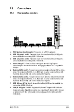
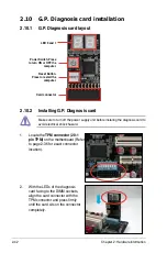
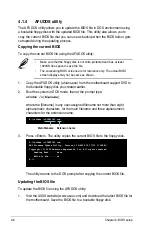
2.10 G.P. Diagnosis card installation
2.10.1 G.P. Diagnosis card layout
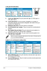
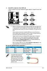
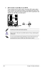
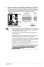
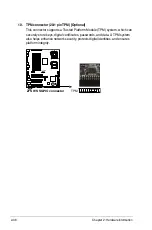
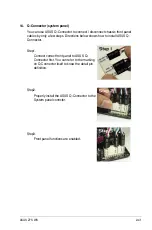
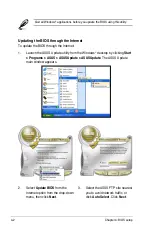
1. Locate the
TPM connector (20-1
pin TPM)
on the motherboard (Refer
to page 2-36 for exact connector
location).
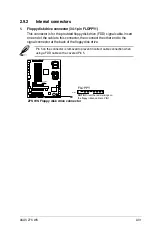
2. With the LEDs of the diagnosis
card facing to the DIMM sockets,
align the card connector with the
TPM connector and press firmly
until the card sits on the connector
completely.
Make sure to turn off the power supply unit before instaling the diagnosis card to
avoid electrical shock hazard.
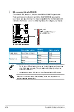
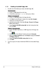
2.10.2 Installing G.P. Diagnosis card
LED 0 and 1
Card connector
Power Switch. Press
to turn ON or OFF the
computer.
Reset Button.
Press to restart the
computer.
Содержание Z7S WS - Motherboard - SSI CEB
Страница 1: ...Motherboard Z7S WS ...
Страница 14: ...xiv ...
Страница 16: ...ASUS Z7S WS Chapter summary 1 1 1 Welcome 1 1 1 2 Package contents 1 1 1 3 Special features 1 2 ...
Страница 66: ...2 44 Chapter 2 Hardware information ...
Страница 67: ...3 Chapter 3 Powering up This chapter describes the power up sequence and ways of shutting down the system ...
Страница 68: ...ASUS Z7S WS Chapter summary 3 3 1 Starting up for the first time 3 1 3 2 Turning off the computer 3 2 ...
Страница 108: ...4 36 Chapter 4 BIOS setup ...
Страница 153: ...A Appendix CPU features The Appendix describes the CPU features and technologies that the motherboard supports ...
Страница 154: ...ASUS Z7S WS Chapter summary A A 1 Intel EM64T A 1 A 2 Enhanced Intel SpeedStep Technology EIST A 1 ...