ASUS TS100-E10-PI4
3-15
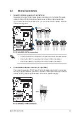
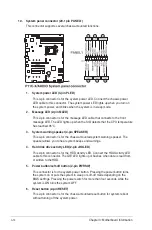
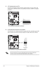
11. Auxiliary panel connector (20-2 pin AUX_PANEL1)
This connector is for additional front panel features including front panel SMB, locator
LED and switch, chassis intrusion, and LAN LEDs.
1. Front panel SMB (6-1 pin FPSMB)
These leads connect the front panel SMBus cable.
2. LAN activity LED (2-pin LAN1_LED, LAN2_LED)
These leads are for the Gigabit LAN activity LEDs on the front panel.
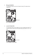
3. Locator LED (2-pin LOCATORLED1, LOCATORLED2)
These leads are for the locator LED1 and LED2 on the front panel. Connect the
Locator LED cables to these 2-pin connector. The LEDs will light up when the
Locator button is pressed.
4. Locator Button/Switch (2-pin LOCATORBTN)
These leads are for the locator button on the front panel. This button queries the
state of the system locator.
Содержание TS100-E10-PI4
Страница 1: ...Pedestal Server TS100 E10 PI4 User Guide ...
Страница 10: ...x ...
Страница 42: ...Chapter 3 Motherboard Information 3 2 3 1 Motherboard layout ...
Страница 60: ...Chapter 3 Motherboard Information 3 20 ...
Страница 118: ...5 18 Chapter 5 RAID Configuration ...
Страница 125: ...ASUS TS100 E10 PI4 6 7 5 Follow the onscreen instructions to complete the installation ...
Страница 126: ...6 8 Chapter 6 Driver Installation ...
Страница 127: ...Appendix This appendix includes additional information that you may refer to when configuring the motherboard Appendix ...
Страница 128: ...A 2 Appendix P11C X AUDIO block diagram ...
Страница 138: ...A 12 Appendix ...


