A S U S R S 1 2 0 - E 3 / P A 4
A S U S R S 1 2 0 - E 3 / P A 4
A S U S R S 1 2 0 - E 3 / P A 4
A S U S R S 1 2 0 - E 3 / P A 4
A S U S R S 1 2 0 - E 3 / P A 4
1 - 5
1 - 5
1 - 5
1 - 5
1 - 5
1.5
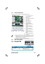
Internal features
The barebone server includes the basic components as shown.
1.
PCI-X and PCI Express x8
riser card bracket
2.
Power fans
3.
ASUS P5MT-R motherboard
4.
Power supply
5.
Device fans (x 2)
6.
System fans (x 4)
7.
SATA backplane
8.
Hot-swap HDD tray 1 -
Connects to SATA1 port
(Port0)
9.
Hot-swap HDD tray 2 -
Connects to SATA2 port
(Port1)
10. Hot-swap HDD tray 3 -
Connects to SATA3 port
(Port2)
11. Hot-swap HDD tray 4 -
Connects to SATA4 port
(Port3)
12. Front I/O board (hidden)
13. Optical drive
•
The barebone server does not include a floppy disk drive. Connect a
USB floppy disk drive to any of the USB ports on the front or rear
panel if you need to use a floppy disk.
•
Only ASUS CD/DVD-ROMs fit the optical drive bay.
2
2
2
2
2
1.6
LED information
1.6.1
1.6.1
1.6.1
1.6.1
1.6.1
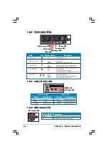
Rear panel LEDs
Rear panel LEDs
Rear panel LEDs
Rear panel LEDs
Rear panel LEDs
L E D
L E D
L E D
L E D
L E D
D i s p l a y s t a t u s
D i s p l a y s t a t u s
D i s p l a y s t a t u s
D i s p l a y s t a t u s
D i s p l a y s t a t u s
D e s c r i p t i o n
D e s c r i p t i o n
D e s c r i p t i o n
D e s c r i p t i o n
D e s c r i p t i o n
Location LED
OFF
Normal status
ON
Location switch is pressed
(Press the location switch again to turn off)
L o c a t i o n L E D
L o c a t i o n L E D
L o c a t i o n L E D
L o c a t i o n L E D
L o c a t i o n L E D
4
4
4
4
4
3
3
3
3
3
1
1
1
1
1
5
5
5
5
5
5
5
5
5
5
6
6
6
6
6
7
7
7
7
7
8
8
8
8
8
1
1
1
1
12
2
2
2
2
1 0
1 0
1 0
1 0
1 0
9
9
9
9
9
1 3
1 3
1 3
1 3
1 3
1
1
1
1
11
1
1
1
1

