background image

Chapter  10  INTERFACE  SETTINGS 


445 


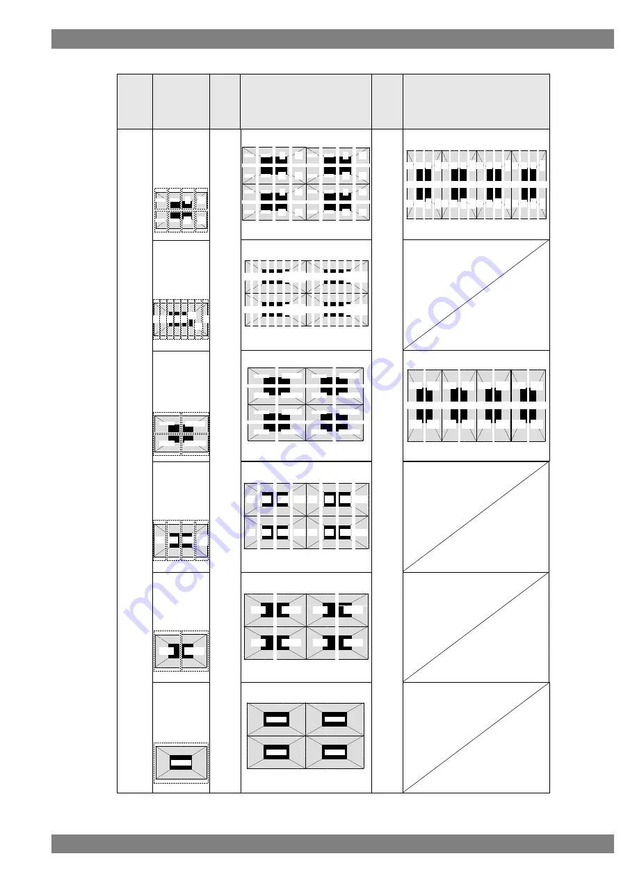
Number of Lane = 16 lanes x 4 (8K4K 120Hz) 


Split Mode

*Mode10 is not 

supported. 

DotClk 

Mode

Pattern Image

Mode0

Mode1

Mode2

Position1

Position2

Multi 

VGMode

Position3

Position4

Position1

Position2

Position3

Position4

Position1

Position2

Position3

Position4

Pattern Image

Position1

Position2

Multi 

VGMode

Position3

Position4

Mode3,7,8

Mode4,5,6

Position1

Position2

Position3

Position4

Position1

Position2

Position3

Position4

CH3/4

 CH1/2

と同じ出力になります

Position1

Position2

Position3

Position4

1/2lane

3/4lane

5/6lane

7/8lane

9/10
lane

11/12

lane

13/14

lane

15/16

lane

1/2lane

3/4lane

5/6lane

7/8lane

9/10
lane

11/12

lane

13/14

lane

15/16

lane

1/2lane

3/4lane

5/6lane

7/8lane

9/10
lane

11/12

lane

13/14

lane

15/16

lane

1/2lane

3/4lane

5/6lane

7/8lane

9/10
lane

11/12

lane

13/14

lane

15/16

lane

1/2lane

3/4lane

5/6lane

7/8lane

9/10
lane

11/12

lane

13/14

lane

15/16

lane

1/2

lane

3/4

lane

5/6

lane

7/8

lane

9/10
lane

11/12

lane

13/14

lane

15/16

lane

1/2

lane

3/4

lane

5/6

lane

7/8

lane

9/10
lane

11/1

2

lane

13/1

4

lane

15/1

6

lane

1/2

lane

3/4

lane

5/6

lane

7/8

lane

9/10
lane

11/1

2

lane

13/1

4

lane

15/1

6

lane

1/2

lane

3/4

lane

5/6

lane

7/8

lane

9/10
lane

11/1

2

lane

13/1

4

lane

15/1

6

lane

1/2

lane

3/4

lane

5/6

lane

7/8

lane

9/10
lane

11/1

2

lane

13/1

4

lane

15/1

6

lane

1/2/3/4lane

9/10/11/12lane

5/6/7/8lane

13/14/15/16lane

1/2/3/4lane

9/10/11/12lane

5/6/7/8lane

13/14/15/16lane

1/2/3/4lane

9/10/11/12lane

5/6/7/8lane

13/14/15/16lane

1/2/3/4lane

9/10/11/12lane

5/6/7/8lane

13/14/15/16lane

1/2/3/4lane

9/10/11/12lane

5/6/7/8lane

13/14/15/16lane

1/2/3/4

lane

5/6/7/8

lane

9/10/11/

12lane

13/14/15

/

16lane

1/2/3/4

lane

5/6/7/8

lane

9/10/11/

12lane

13/14/15/

16lane

1/2/3/4

lane

5/6/7/8

lane

9/10/11/

12lane

13/14/15/

16lane

1/2/3/4

lane

5/6/7/8

lane

9/10/11/

12lane

13/14/15/

16lane

1/2/3/4

lane

5/6/7/8

lane

9/10/11/

12lane

13/14/15/

16lane

Mode9

H2/V2Div

Quad

(16 Lanes)

V4Div

1/2/

・・・

/7/8

lane

9/10/

・・・

/15/16

lane

1/2/

・・・

/7/8

lane

9/10/

・・・

/15/16

lane

1/2/

・・・

/7/8

lane

9/10/

・・・

/15/16

lane

1/2/

・・・

/7/8

lane

9/10/

・・・

/15/16

lane

1/2/

・・・

/7/8

lane

9/10/

・・・

/15/16

lane

CH1/2/3/4

CH1/2/3/4

Position1

Position2

Position3

Position4

CH1/2/3/4

CH1/2/3/4

CH1/2/3/4

1/2la

ne

3/4la

ne

5/6la

ne

7/8la

ne

9/10
lane

11/1

2

lane

13/1

4

lane

15/1

6

lane

1/2la

ne

3/4la

ne

5/6la

ne

7/8la

ne

9/10
lane

11/1

2

lane

13/1

4

lane

15/1

6

lane

1/2la

ne

3/4la

ne

5/6la

ne

7/8la

ne

9/10
lane

11/1

2

lane

13/1

4

lane

15/1

6

lane

1/2la

ne

3/4la

ne

5/6la

ne

7/8la

ne

9/10
lane

11/1

2

lane

13/1

4

lane

15/1

6

lane

1/2/3/4lan

e

9/10/11/1

2lane

5/6/7/8lan

e

13/14/15/

16lane

1/2/3/4lan

e

9/10/11/1

2lane

5/6/7/8lan

e

13/14/15/

16lane

1/2/3/4lan

e

9/10/11/1

2lane

5/6/7/8lan

e

13/14/15/

16lane

1/2/3/4lan

e

9/10/11/1

2lane

5/6/7/8lan

e

13/14/15/

16lane

Содержание VG-876

Страница 1: ...Video Signal Generator VG 876 Instruction Manual Ver 3 40 ...

Страница 2: ......

Страница 3: ... 9 1 5 2 Exchanging modules 9 1 5 3 Firmware version up 11 1 5 4 Checking operation 11 1 6 Menu lists 12 1 6 1 Program Edit menu list 12 1 6 2 Group Edit menu list 14 1 6 3 Audio Edit menu list 14 1 6 4 DP Analysis menu list 14 1 6 5 Data Copy Erase menu list 14 1 6 6 Configuration menu list 15 1 6 7 Audio Flash Data Entry 15 1 6 8 Maintenance menu list 15 Chapter2 OPERATION PROCEDURES 17 2 1 Flow...

Страница 4: ...1 Types of color bar patterns 44 4 1 2 Color bar pattern customizing 45 4 2 Gray scale patterns 47 4 2 1 Types of gray scale patterns 47 4 2 2 Gray scale pattern customizing 48 4 3 Ramp patterns 50 4 3 1 Types of ramp patterns 50 4 3 2 Ramp pattern type settings and customizing 51 4 4 Sweep patterns 53 4 4 1 Types of sweep patterns 53 4 4 2 Sweep pattern selection 54 4 5 Monoscope patterns 55 4 5 ...

Страница 5: ...2 2 Cursor operations 99 4 13 Name List 101 4 13 1 Name List display 102 4 13 2 Name 103 4 13 3 EDID 105 4 13 4 DDC CI 107 4 13 5 HDCP High bandwidth Digital Content Protection 110 4 13 6 HDMI list 114 4 13 7 Timing data list 115 4 13 8 Image pattern list 116 4 13 9 OPT USER pattern list 116 4 13 10 Subtitle 117 4 13 11 SCDC 119 4 14 Video black white reversal 122 4 15 Simple animation 123 4 15 1 ...

Страница 6: ...169 7 1 6 INC DEC interval setting 170 7 1 7 Color depth setting 170 7 1 8 SAMPLE RGB YPbPr setting 171 7 1 9 DDC clock setting 171 7 1 10 Trigger mode settings 172 7 1 11 Image priority settings 182 7 1 12 Image Position Setting 183 7 1 13 Cursor coordinate setting 184 7 1 14 Mouse speed setting 184 7 1 15 Digital Video Level Step setting 185 7 1 16 High speed drawing mode setting 185 7 1 17 CUST...

Страница 7: ...irm data size of each interface unit 220 9 6 2 Delete the data of output interface unit 221 9 6 3 Select the interface unit to version up 222 Chapter10 INTERFACE SETTINGS 224 10 1 VG 876 interface units 224 10 1 1 HDMI unit VM 1876A M0 224 10 1 2 DisplayPort unit VM 1876 M1 this unit is discontinued 224 10 1 3 DisplayPort Unit VM 1876A M1 225 10 1 4 V by One HS unit VM 1876 M2 226 10 1 5 SDI IF BO...

Страница 8: ...function 285 10 3 8 EDID 287 10 3 9 HDCP 287 10 3 10 DDC CI 288 10 3 11 LipSync 288 10 3 12 ARC 288 10 3 13 HPD Negate 293 10 4 DisplayPort 294 10 4 1 Connector and pin assignment 294 10 4 2 Split setting 295 10 4 3 DisplayPort setting 299 10 4 4 Displaying the DisplayPort setting information 306 10 4 5 DP Analysis 311 10 4 6 Embedded audio 315 10 4 7 EDID 316 10 4 8 HDCP 316 10 4 9 DDC CI 316 10 ...

Страница 9: ... Audio sweep settings 432 10 9 3 AAC AC3 Audio Data Entry 433 10 9 4 Flash Data Entry 434 10 10 Analog Audio 435 10 10 1 Connectors and output signals 435 10 10 2 Analog audio signals 435 10 11 Synchronization by several units operation 437 10 11 1 Outline 437 10 11 2 Connection 438 10 11 3 VM 1876 MX setting 440 10 11 4 Control operation 441 10 11 5 Split Mode Image of 4 units synchronization 443...

Страница 10: ...consumption of the DDC DP_PWR power supply 488 10 19 License list 489 Chapter11 FUNCTIONS AVAILABLE WITH TV STANDARD SIGNALS 491 11 1 Macrovision 491 11 1 1 Description and specifications 491 11 1 2 Setting procedure 492 11 2 Closed captions V Chip 493 11 2 1 Description and specifications 493 11 2 2 Closed caption settings 494 11 2 3 V Chip settings 499 11 3 Teletext 504 11 3 1 Description and sp...

Страница 11: ...Contents ix Chapter13 SCREEN SPLIT IMAGE LIST 519 13 1 Single clock mode Image split 519 13 2 Dual clock mode Image split 520 13 3 Quad clock mode Image split 522 Chapter14 Revision history 525 ...

Страница 12: ...pliance or inside a high pressure vessel Doing so may heat up the generator to abnormally high levels cause smoking running the risk of the generator s catching fire and or damaging the circuit components This generator contains some high voltage parts If you touch them you may receive an electric shock and burn yourself so do not attempt to disassemble repair or remodel the generator If there is ...

Страница 13: ...traight away instead turn on the power of the VG 876 and allow it to warm up for about 10 to 15 minutes before use so as to ensure that the VG 876 will operate stably Never unscrew and open the cover on the side panel of the main unit while the main unit power is turned on Malfunctioning may result if the cover or the screw should drop into the chassis of the main unit Concerning impact This is a ...

Страница 14: ...P 8870 software installation CD for Windows 1 pc SP 8870 instruction manual PDF version packed with the SP 8870 software installation CD Power cable 1 pc 1 FG cable 1 5 meters long 1 pc 1 1 These cables are designed to be used exclusively with the VG 876 Optional accessories RB 1870 Remote control box used exclusively with the VG 876 RB 1871 Simplified remote control box used exclusively with the ...

Страница 15: ...B connector Full variety of sample data incorporated inside A total of a thousand types of timing data and a thousand types of pattern data are registered inside the VG 876 as sample data They are categorized by standard application and other factors and it is possible for the data required to be selected easily Registration of program data on USB memory A total of a thousand program data can be r...

Страница 16: ...patterns 16 F0h to FFh The various data can be registered in the internal memory approx 60 MB of the VG 876 or in USB Memory Number of data Program data 1000 Program 1 to 1000 User option patterns 999 1 to 999 Images image data 999 1 to 999 Number of data depends on the image data size memory capacity and card capacity User character patterns 16 E0H to EFH Number of characters in program names 20 ...

Страница 17: ...DOW B R B P G Y R P NAME LIST CURSOR CATEGORY SAMPLE TIMING PATTERN GROUP INV SYNC ACTION LEVEL SET DETAIL ESC SHIFT SAVE RASTER ASPECT CHECKER IMAGE OPTION ABC MUTE SHORT CUT 0 STATUS MENU DEC INC 1 3 2 4 A 6 C 5 B 7 D 8 E 9 F HDCP GRAY MONOSCOPE SWEEP RAMP COLOR DIGITAL VIDEO GENERATOR VG 876 B A E F C D G ...

Страница 18: ...eys default I HDCP II MUTE Change levels digital video levels only For further details on the keys refer to 1 4 3 Names of the keys and their functions REMOTE BOX RB 1870 MENU SHORT CUT 9 F 6 C 5 B 4 A 7 D 8 E SHIFT SAVE 3 0 1 INC 2 DEC STATUS TIM ESC GROUP CATEGORY SET PAT SAMPLE GRAY COLOR SWEEP MONOSCOPE G Y CURSOR ASPECT RASTER WINDOW R P ABC LEVEL IMAGE OPT CHECKER B P NAME LIST INV ACTION DE...

Страница 19: ...OM Key B Menu operation screens The menu screens are used to set and check the items displayed on the fluorescent display tube C Rotary switch This is turned clockwise or counterclockwise to select the setting items or parameters change the level settings etc D Number keys to Used to input numerical values select the menus etc INC DEC Used to select the setting items or parameters change the level...

Страница 20: ... when only the output pattern data is to be changed Group key Used to display user registered groups etc and create groups Escape key This key can be used in the following situations When canceling parameter selections or numerical value settings When returning the displayed menu screen to the previous hierarchical level Set key Used to enter the setting items and parameters which have been set F ...

Страница 21: ...s connector supports a regular USB mouse for cursor patterns operation By using the pointer of the mouse cursor pattern can be operated N USB 2 This connector is used to connect the generator with a PC to enable the VG 876 to be operated using the SP 8870 software etc Refer to the instruction manual of the SP 8870 software for further details O LAN port This port is used for connection to a LAN us...

Страница 22: ...e used only by the VG 876 main unit RB 1870 These enable all the generator functions to be operated This remote control box makes it possible to perform the same operations as the ones which are performed on the front panel of the VG 876 RB 1871 Programs can be read only This is a simplified remote control box which is intended for use on production lines SP 8870 These enable all the generator fun...

Страница 23: ...w versions of current standards and to new interfaces For further details on the VM 1876 series refer to 10 1 VG 876 video units 1 5 2 Exchanging modules Users can exchange VM modules When you install VM 1876 modules insert it from IF OUT1 Maximum 4 modules can be installed in IF OUT1 to IF OUT4 As for VM 1876 MX install it in IF IN slot Output unit slot Input unit slot Insert output units from IF...

Страница 24: ...10 Hold 2 screws of rear side and exchange it Be careful that the components on the VM modules not to touch the main unit of VG 876 CAUTION ...

Страница 25: ...irmware version up is necessary when you install new VM 1876 interface units Please ask ASTRODESIGN about the latest firmware data 1 5 4 Checking operation The LED of ST BY of the rear of VM 1876 is lit as green when it works normally Make sure it is lit as green ...

Страница 26: ...ndicate setting items 1 6 1 Program Edit menu list Program Edit Program Name Timing H Timing V Timing Output All Output Output OFF ON HDMI DP V by One HS SDI Analog Output Output OFF ON General Audio OFF ON Digital Output General HDMI Output OFF ON InfoFrame Packet Vendor Specific InfoFrame AVI InfoFrame SPD InfoFrame Audio InfoFrame MPEG InfoFrame NTSC VBI InfoFrame Dynamic Range InfoFrame ACP Pa...

Страница 27: ...Ramp Sweep Monoscope Raster Aspect AFD Checker Image OPT 9 Marker 3D Image 3D Pattern ABC Color Character Cross Hatch Dot Circle Burst Window Cursor Name List NAME Subtitle HDCP EDID DDC CI CEC HDMI ARC DP Action Graphic Plane Character Plane Window Subtitle Motion Blur 0 125dot Scroll option Scroll Sequence Lip sync Black Insertion ...

Страница 28: ...py Erase menu list Data Copy Erase COPY Program COPY USER Character COPY USER OPT Pattern COPY Image COPY Subtitle COPY Group COPY Auto COPY All ERASE Program ERASE USER Character ERASE USER OPT Pattern ERASE Image ERASE Subtitle ERASE Group ERASE Auto ERASE All Only the Program directory is shown in the Group Edit menu list Only the Setting directory is shown in the Auto Edit menu list Displayed ...

Страница 29: ... Audio Flash Data Entry Group No 1 6 8 Maintenance menu list Maintenance Information INITIAIZE Configuration INITIAIZE SHORTCUT UNMOUNT USB SAVE USB CONFIG STAUS FORMAT Internal Memory INSTALL Initial Data ADJUST VGA YPbPR ADJUST COMPOSITE Only the directory names are displayed in the Configuration menu list The Maintenance menu list shows only displayed directories The Audio Flash Data Entry menu...

Страница 30: ...16 ...

Страница 31: ...his generator the timing data and pattern data are collectively referred to as the program data Program data Timing data Video timing data settings Horizontal timing Vertical timing Audio output settings Sound source level Frequency On or off of channels Output settings On or off for each interface Settings inherent to interfaces Pattern data Patter data settings Type size level and other settings...

Страница 32: ...splay patterns are not changed 2 Select the timing data from the categories The timing data of the internal sample data is classified by category such as EIA or VESA PC Select the desired timing data from the category which contains it 1 2 Select the category using or and then press 3 Select the timing data using or and then press Video timing data output The display patterns are not changed SAMPL...

Страница 33: ...ta 1 Inputting the pattern data numbers directly 1 Input the pattern data number 1001 to 1999 using number keys to Refer to 1 1 1 Program Data in the Supplementary Manual The corresponding pattern is displayed etc 2 Selecting the pattern data from the categories 1 The pattern category is displayed 2 Select the category using or and then press 3 Select the pattern using or and then press The patter...

Страница 34: ... displayed Lighted selected off deselected 2 When setting details for the pattern or changing the pattern type Press The pattern selection screen is displayed 3 Select the pattern using or and then press The selected pattern is displayed Select the pattern directly using the number keys to Press to select COLOR ABC COLOR COLOR DETAIL INC DEC SET 0 STATUS 9 F 4 A ...

Страница 35: ...Check this to select the bitmap image or an optional pattern Character Check this to select the character pattern Cross Hatch Check this to select the crosshatch pattern Dot Check this to select the dot pattern Check this to select the frame pattern Check this to select the cross pattern Check this to select the center marker pattern Circle Check this to select the circle pattern Burst Check this ...

Страница 36: ...is to flicker the window W LEVEL Check this to change the window level W L SEQ Check this to execute the window level sequence M BLUR Check this to execute motion blur S SCROLL Check this to scroll the subtitle pattern 3 Select the action using or and then press On this screen the scroll direction and number of steps are set when the GC SCROL G SCROLL or C SCROLL action has been checked Select the...

Страница 37: ...en the W LEVEL action has been checked UP Select this to increment the level DOWN Select this to decrement the level STOP Select this to temporarily stop the level change STEP 1 Select this to increment the level change step by 1 STEP 1 Select this to decrement the level change step by 1 EDIT Select this to perform the detailed level settings 6 Select the action using or and then press On this scr...

Страница 38: ... 3 Select the item using or and then press One of the following actions is selected and the detailed settings are performed For details on the setting procedure refer to ACTION SETTINGS in Chapter 5 Graphic Plane Character Plane Window Subtitle Motion Blur 0 25 0 125 dot Scroll Lip Sync Black Insertion MENU INC DEC SET INC DEC SET INC DEC SET ...

Страница 39: ...e containing up to 20 characters can be allocated as the program name Pattern Name Any name containing up to 20 characters can be allocated as the pattern name 3 Select using or and then press The program data is saved For further details refer to 7 1 11 Image priority settings SAVE INC DEC SET INC DEC SET If USB Memory has been inserted the data registered in the USB Memory will be enabled and th...

Страница 40: ...e name is to be input changes To delete all the characters All the characters already input for the name are cleared To delete one character The character at the cursor position is deleted To change character insert overwrite Use this to switch between inserting and overwriting the characters Insert is switched to overwrite or vice versa To input characters Select the characters using and enter th...

Страница 41: ... programs can be registered in a group Up to 99 groups can be registered 2 4 1 Executing groups The combinations of programs and patterns which are used with a high frequency and which have been registered by the user can be executed 1 2 Select the groups using or and then press Only the programs registered as groups can be selected 3 Select the groups using or and then press The programs in the g...

Страница 42: ... executed in sequence from 01 up to 98 If 0 is set for both TIM and PAT If 0 is set for Program In both of the above cases 0 is recognized as the end of the group When TIM PAT is selected as the Edit Mode setting When Program is selected as the Edit Mode setting TIM PAT The program numbers are set in this column TIM The timing data numbers are listed here PAT The pattern data numbers are listed he...

Страница 43: ...se DP Name Pattern Mode Configuration SDI GroupMode NameDisp Select items by using or The below menu is displayed Selecting the items Select the items of GroupMode NameDisp by using INC DEC key and then press SET key Alternatively select the items using the number keys 0 STATUS to 9 F and then press SET key Setting the parameters Select the parameters using Rotary switch or INC DEC key and then pr...

Страница 44: ...Start Stop The start and end points of programs to be repeated are set here The start and end point settings can be designated in three stages Automatic execution is performed in the following sequence Start point 1 end point 1 start point 2 end point 2 start point 3 end point 3 When Group has been selected as the Mode setting Group No The number of the group to be executed automatically is set he...

Страница 45: ...tic execution at any time press 6 Select Auto Data SAVE using or 7 Select the save destination at Media using or and then press Select EXECUTE using or and then press Internal The data is saved on the internal memory USB Memory The data is saved in the USB Memory INC DEC SET ESC SAVE INC DEC INC DEC SET INC DEC SET ...

Страница 46: ...t to some restrictions For details refer to 10 12 1 Common specifications Period Time display 0 00 to 999 999 μs Dot display 128 to 9998 dots μs setting fixed using SHIFT 2 dot setting fixed using SHIFT 3 Disp Time display 0 00 to 999 999 μs Dot display 48 to 8192 dot μs setting fixed using SHIFT 0 dot setting fixed using SHIFT 1 Backp Sync Time display 0 00 to 999 999 μs Dot display 0 to 9998 dot...

Страница 47: ... Frontp Frontp Period Disp Sync Backp Time display 0 00 to 999 999 μs Dot display 0 to 8192 dots Setting units are restricted depending on the Dot Clock operation mode DotClk Mode Refer to 10 2 4 Dot Clock Operation Mode Dot Clk Mode for details CAUTION When items are set in microseconds μs restrictions apply to these settings depending on the dot clock frequency and other timing data used for dra...

Страница 48: ...arameters to μs time microseconds or dot number of dots dots Dot Clock The dot clock frequency MHz is set here Repetition The number of repetitions is set here The pixel configuration depends on the number which is set in Repetition When 2 is set for Repetition and 1440 for Disp the number of pixels will be 720 Period The total number of pixels in the horizontal direction is set here When μs time ...

Страница 49: ...cal timing data editing The vertical timing setting locations and names of the settings are indicated below 3 2 1 Vertical timing data For progressive scanning For interlaced scanning Serration EQP Fp EQP Bp VDstart VDline Disp Backp Sync Total ...

Страница 50: ...ter fixing function Field 1 Total1 Time display 0 00 to 999 999 ms Dot display 4 0 to 4096 0 H in 0 5H increments Fixed to ms setting using SHIFT 2 Fixed to H setting using SHIFT 3 Disp1 Time display 0 00 to 999 999 ms Dot display 1 to 2560 H Fixed to ms setting using SHIFT 0 Fixed to H setting using SHIFT 1 Sync1 Time display 0 00 to 999 999 ms Dot display 1 0 to 99 0 H in 0 5H increments Backp1 ...

Страница 51: ...scanning Item Calculation formula Setting range Frontp1 Frontp2 Frontp1 Total2 Disp2 Sync2 Backp2 Frontp2 Total1 Disp1 Sync1 Backp1 Time display 0 00 to 999 999 ms Dot display 0 0 to 4096 0 H Blanking1 Blanking2 Blanking1 Frontp1 Sync1 Backp1 Blanking2 Frontp2 Sync2 Backp2 Time display 0 00 to 999 999 ms Dot display 2 0 to 4096 0 H Setting units are restricted depending on the Dot Clock Operation ...

Страница 52: ...then press SET key Alternatively select the parameters using the number keys 0 STATUS to 9 F and then press SET key V Timing parameters Input Mode Select the input setting for the V Timing parameters to ms time milliseconds or H number of lines H Scan Refer to 3 2 4 Concerning the scanning modes TV Mode As a general rule do not change this setting For further details refer to 3 2 5 Concerning the ...

Страница 53: ...laced scanning Different pixels are drawn in the first field and second field Operation is performed for each frame 2 fields Interlace Sync Interlaced scanning The same image is repeatedly drawn in the first field and second field Operation is performed for each field 3 2 5 Concerning the TV modes This parameter indicates the output of the TV standard signals NTSC NTSC M NTSC 443 PAL PAL M PAL 60 ...

Страница 54: ...cribed using the table below Serration and EQP setting procedure Setting item Key LCD display Description Serration 0 OFF Serrated pulses are not inserted 1 0 5H Serrated pulses are inserted in increments of 0 5H 2 1H Serrated pulses are inserted in increments of 1H 3 EXOR HS and VS EXORs are inserted as serrated pulses EQP 0 OFF Equalizing pulses are not inserted into the EQPfp and EQPbp periods ...

Страница 55: ...d for Serration Hperiod Hsync Vsync Hsync Hperiod 1 2 Hperiod CS VS HS The serration and EQP item settings are not reflected in the composite Y C and SCART signals In the case of HDTV timing data they are set to OFF when EXOR is selected as the serration setting item CAUTION ...

Страница 56: ... the equalizing pulse inside the back porch Setting range 0 000 to 999 999 ms 0 to 99 H For interlaced scanning Setting item Details of setting EQP Fp1 EQP Fp2 This sets the equalizing pulse inside the front porch Setting range 0 000 to 999 999 ms 0 0 to 99 0 H in 0 5H increments EQP Bp1 EQP Bp2 This sets the equalizing pulse inside the back porch Setting range 0 000 to 999 999 ms 0 0 to 99 0 H in...

Страница 57: ...Chapter 3 TIMING DATA SETTINGS 43 ...

Страница 58: ...es listed below For further details on pattern selection refer to 2 1 3 Selecting the pattern data 0 CUSTOM Customized pattern 75 75 color bars SMPTE color bars 1 100 100 H 100 100 color bars 2 100 75 H 100 75 color bars 3 75 75 H 75 75 color bars 4 SMPTE SMPTE color bars 5 RGBW V Horizontal color bars 6 xvYCC 4 xvYCC 4 color bars 7 xvYCC 8 xvYCC 8 color bars 8 xvYCC 12 xvYCC 12 color bars ...

Страница 59: ... Copy Erase Pattern Sweep Select item using or The Color Bar screen is displayed Selecting the items 1 Select Type 2 Select the items of Color Bar using Rotary switch or INC DEC key and then press SET key Alternatively select the items using the number keys 0 STATUS to 9 F and then press SET key For further details on the patterns refer to 4 1 1 Types of color bar patterns Detailed settings of cus...

Страница 60: ...e per color is set here 0 The size is set as a percentage of the entire screen 1 Dot The size is set in 1 dot increments 4 Width Width dot The display size per color is set here When a percentage is used for Input Mode Set any width from 0 0 to 100 0 When dots are used for Input Mode Set the width in 1 dot increments 5 Color Level The display color and level are set here Number The colors from 1 t...

Страница 61: ...ale patterns can be selected from among the types listed below For further details on pattern selection refer to 2 1 3 Selecting the pattern data 0 CUSTOM Customized pattern 16Step H 16Step V 1 8Step H 8 steps horizontal 2 16Step H 16 steps horizontal 3 32Step H 32 steps horizontal 4 8Step V 8 steps vertical 5 16Step V 16 steps vertical 6 32Step V 32 steps vertical ...

Страница 62: ...p Select item using or The Gray Scale screen is displayed Selecting the items 1 Select Type 2 Select the items of Gray Scale using Rotary switch or INC DEC key and then press SET key Alternatively select the items using the number keys 0 STATUS to 9 F and then press SET key For further details on the patterns refer to 4 2 1 Types of gray scale patterns Detailed settings of customized patterns 3 Se...

Страница 63: ...of specifying the display size per step is set here 0 The size is set as a percentage of the entire screen 1 Dot The size is set in 1 dot increments 4 Width Width dot The display size per step is set here When a percentage is used for Input Mode Set any size from 0 0 to 100 0 When dots are used for Input Mode Set the size in 1 dot increments 5 Level The display level is set here Number The steps f...

Страница 64: ...r H 2 Linear V 3 Linear 256 4 RGB1 5 RGB2 6 RGB3 7 Turn H 8 Linear GR 9 Linear BR A Linear BG B Linear RG C Linear RB D Linear GB E Linear HV F Limited H Limited V H2 UpUp H2 DownUp H2 UpDown H2 DownDwn V2 UpUp V2 DownUp V2 UpDown V2 DownDwn 1 After Limited V is selectable only by or 2 The luminance level of Limited H V is 16 232 and color difference level is 16 240 3 The luminance level from H2 U...

Страница 65: ...o Ramp Data Copy Erase Pattern Sweep Select item using or The Ramp screen is displayed Selecting the items 1 Select Type 2 Select the items of Ramp using Rotary switch or INC DEC key and then press SET key Alternatively select the items using the number keys 0 STATUS to 9 F and then press SET key For further details on the patterns refer to 4 3 1 Types of ramp patterns Detailed settings of customi...

Страница 66: ... of display steps from the start level to end level is set here Setting range 1 setting End Start 1 The setting range for the above levels differs depending on the color depth 8 BIT 0 to 255 9 BIT 0 to 511 10 BIT 0 to 1023 11 BIT 0 to 2047 12 BIT 0 to 4095 13 BIT 0 to 8191 14 BIT 0 to 16383 15 BIT 0 to 32767 16 BIT 0 to 65535 Concerning H Line This item takes effect only when 0 has been selected a...

Страница 67: ...en sweep is selected using the pattern key for instance sweep patterns can be selected from the types listed below For further details on pattern selection refer to 2 1 3 Selecting the pattern data 0 Multi Burst 100 Multi burst Multi burst 1 Multi Burst 50 Multi burst 2 Sweep Sweep ...

Страница 68: ...se Pattern Sweep Select item using or The Sweep screen is displayed Selecting the items 1 Select Type 2 Select the items of Sweep using Rotary switch or INC DEC key and then press SET key Alternatively select the items using the number keys 0 STATUS to 9 F and then press SET Setting the parameters Select the parameters using Rotary switch or INC DEC key and then press SET key Alternatively select ...

Страница 69: ...PDC1 to APDC5 are used to evaluate movie resolution These patterns are an option For further details contact ASTRODESIGN sales representative or your dealer 2 This is the check pattern which is used only for SDI outputs It is output only from SDI outputs The output timing is limited as below SDI Check Field supported format SD 480 59 94i 575 50i HD 1920x1080 YCbCr 4 2 2 10bit 60i 59 94i 50i 30p 29...

Страница 70: ...ess SET key Alternatively select the items using the number keys 0 STATUS to 9 F and then press SET key Setting the parameters Select the parameters using Rotary switch or INC DEC key and then press SET key Alternatively select the parameters using the number keys 0 STATUS to 9 F and then press SET key For further details on the patterns refer to 4 5 1 Types of monoscope patterns When type setting...

Страница 71: ...e procedure for selecting the types of raster patterns and for performing the settings when CUSTOM has been selected as the raster pattern type The rasters can be displayed with any level MENU ProgramEdit Pattern Raster ProgramEdit Program Name Gray Scale Type GroupEdit Timing Ramp CUSTOM AutoEdit Output Sweep DP Analysis Audio Monoscope Data Copy Erase Pattern Raster Select item using or The Rast...

Страница 72: ...Rotary switch or INC DEC key and then press SET key Alternatively select the parameters using the number keys 0 STATUS to 9 F and then press SET key The setting range for the above R G B levels differs depending on the color depth 8 BIT 0 to 255 9 BIT 0 to 511 10 BIT 0 to 1023 11 BIT 0 to 2047 12 BIT 0 to 4095 13 BIT 0 to 8191 14 BIT 0 to 16383 15 BIT 0 to 32767 16 BIT 0 to 65535 ...

Страница 73: ... can be selected from types listed below For further details on pattern selection refer to 2 1 3 Selecting the pattern data 0 Over Scan Over Scan AFD pattern 1 AFD 0 As the coded frame 1 4 3 center 2 16 9 center 3 14 9 center 4 box 16 9 top 5 box 14 9 top 6 box 13 7 center 7 box 2 1 center 8 box 11 5 center 9 box 12 5 center A 4 3 14 9 center B 16 9 14 9 center C 16 9 4 3 center ...

Страница 74: ... Pattern X ABC Select item using or The Aspect screen is displayed Selecting the items 1 Select Type 2 Select the items of Aspect using Rotary switch or INC DEC key and then press SET key Alternatively select the items using the number keys 0 STATUS to 9 F and then press SET key For further details on the patterns refer to 4 71 Types of aspect ratio patterns Detailed settings of customized pattern...

Страница 75: ...7 1 Types of aspect ratio patterns 3 Color Circle Display the circle level The R G and B levels are displayed in sequence from the left The setting range for the above level differs depending on the color depth 8 BIT 0 to 255 9 BIT 0 to 511 10 BIT 0 to 1023 11 BIT 0 to 2047 12 BIT 0 to 4095 13 BIT 0 to 8191 14 BIT 0 to 16383 15 BIT 0 to 32767 16 BIT 0 to 65535 Back Set the background level Details...

Страница 76: ...rns When checkerboard is selected using the pattern keys or other keys any of the following types of patterns can be selected For further details on pattern selection refer to 2 1 3 Selecting the pattern data 0 DOT DOT Dot 1 BLOCK BLOCK Block 2 SubPixel Sub pixel ...

Страница 77: ...ing or The Checker screen is displayed Selecting the items 1 Select Type 2 Select the items of Checker using Rotary switch or INC DEC key and then press SET key Alternatively select the items using the number keys 0 STATUS to 9 F and then press SET key For further details on the patterns refer to 4 8 1 Types of checkerboard patterns Setting the parameters Select the parameters using Rotary switch ...

Страница 78: ...ll be set regardless of the settings Setting example H 2 V 3 4 SubPixel Offset H V Valid only when Sub Pixel is selected as the Type setting Set the number of sub pixels at the top left in the horizontal H direction and the number of pixels at the very top in the vertical V direction The Sub Pixel H and V settings subsequently apply Setting range 0 to 2 When RGB 0 100 is selected for Color Select ...

Страница 79: ...indicated by 100 In the case of the Sub Pixel item the same level as the RGB level is set The setting range is the same as for User Color 1 4 9 Image OPT 4 9 1 Types of Image OPT When Image OPT has been selected using the pattern key for instance optional and image patterns can be selected from among the types listed below For further details on pattern selection refer to 2 1 3 Selecting the patte...

Страница 80: ...cting the items 1 Select Type 2 Select the items of Image OPT using Rotary switch or INC DEC key and then press SET key Alternatively select the items using the number keys 0 STATUS to 9 F and then press SET key Setting the parameters Select the parameters using Rotary switch or INC DEC key and then press SET key Alternatively select the parameters using the number keys 0 STATUS to 9 F and then pr...

Страница 81: ...GroupEdit Timing Aspect Type AutoEdit Output Checker 9 Marker DP Analysis Audio Image OPT 3D Image Data Copy Erase Pattern X ABC 3D Pattern Select item using or The 9 Marker screen is displayed Selecting the items Select the items of 9 Marker using Rotary switch or INC DEC key and then press SET key Alternatively select the items using the number keys 0 STATUS to 9 F and then press SET key Setting...

Страница 82: ...et here Setting range 0 to 4095 dot 7 Mark Direction H V The direction of the straight line marker is set here 0 H Horizontal line 1 V Vertical line 8 Mark Color R G B The color of the markers is set here The setting range differs depending on the color depth See below 9 Line Mode 0 3 Whether to display the lines and the shape of the lines when they are displayed are set here 0 None No lines 1 V L...

Страница 83: ...No GroupEdit Timing Aspect Type AutoEdit Output Checker 9 Marker DP Analysis Audio Image OPT 3D Image Data Copy Erase Pattern X ABC 3D Pattern Select item using or The 3D Image screen is displayed Selecting the items Select the items of 3D Image using Rotary switch or INC DEC key and then press SET key Alternatively select the items using the number keys 0 STATUS to 9 F and then press SET key Sett...

Страница 84: ...evel L R Level of Right and Left pattern can be changed Setting range 0 100 8 Off Color R G B Set a color of OFF frame or OFF field when you set OFF in L R ON OFF or L R Field ON OFF Setting range 0 255 9 Output Mode 0 1 Set pattern output mode 0 HDMI 3D Structure Pattern is output referring to the setting of HDMI 3D Structure This setting is commonly used 1 Frame Sequential The left and the right...

Страница 85: ...ach right and left picture You select Image No to each picture Image should be saved beforehand Example 1080 FramePacking 1 Monoscope Right and left picture display Monoscope refer to section 4 5 pattern 2 China Right and left picture display China Monoscope refer to section 4 5 pattern Left Right ...

Страница 86: ... Name Raster No GroupEdit Timing Aspect Type AutoEdit Output Checker 9 Marker DP Analysis Audio Image OPT 3D Image Data Copy Erase Pattern X ABC 3D Pattern Select item using or The 3D Pattern screen is displayed Selecting the items Select the items of 3D Pattern using Rotary switch or INC DEC key and then press SET key Alternatively select the items using the number keys 0 STATUS to 9 F and then p...

Страница 87: ...00 5 Off Color R G B The output color when Off has been selected as the L R ON OFF or L R Field ON OFF is set here Setting range 0 255 6 Output Mode 0 1 The pattern output mode is specified here 0 HDMI 3D Structure The HDMI 3D Structure setting is reference and output Normally this setting is specified 1 Frame Sequential The left L and right R patterns are drawn in the VRAM using one frame for eac...

Страница 88: ...as the Type setting This is the same setting as the regular checkerboard pattern Refer to section 4 8 Checkerboard patterns 15 Window Circle Set a parameter of Window Circle that is selected in Type Type 0 3 Select kinds of pattern 0 Window Draw one Window 1 Circle Draw one Circle 2 9 Window Draw 9 Windows 3 9 Circle Draw 9 Circles Real Circle 0 1 In Type if you select Circle or 9 Circle select if...

Страница 89: ... are displayed for left and right respectively LEFT RIGHT 1 Color Bar V 2 The vertical color bar shown in the figures below are output at the left and right LEFT RIGHT LR combination 2 Vertical Bar Vertical bars each consisting of one dot are output The pattern is the same for the left and right L side R side L side R side L side R side 1dot ...

Страница 90: ...or the pattern on the left are reversed from the colors in the pattern on the right The figures below show patterns where the number of blocks is defined as H 4 V 4 LEFT RIGHT 5 Slant Color Bar 6 Slant Gray Bar The different width color bar gray bar in the slant direction The right and the left output the same picture The drawing angle can be changed from 0 165 degrees 7 Raster A raster is output ...

Страница 91: ...in the designated position The left and right frame shows the same picture but color can be set separately 9 3 9 Window 9 4 9 Circle 9 Window patterns are displayed in the designated position The left and right frame shows the same picture but color can be set separately 10 Cross Hatch Cross hatch is output The left and right frame shows the same picture but color can be set separately ...

Страница 92: ...clear Example Side by Side If Sub Sampling is ON the pattern is displayed according to the setting in the 3D Extension Data in the Vender Specific Infoframe e g Type Example Top Bottom If Sub Sampling is ON only Odd lines are drawn in each left and right picture e g Type If Sub Sampling is OFF all lines are drawn by the size of Sub Sampling ON e g Type ...

Страница 93: ...er infiormation is BI_RGB File nane The file name should be like bitmap001 bmp bitmap002 bmp 001 or 002 part are designated number from 001 to 999 Then save it in bmp4 folder of USB memory USB Memory bmp4 folder bitmap001 bmp bitmap002 bmp bitmap003 bmp 1 bitmap003 vgd 1 bitmap004 vgd bitmap005 TestImage01_1920x1080_24bit bmp 2 bitmap006 TestImage02_1920x1080_24bit vgd 2 bitmapname003 vgd 3 bitmap...

Страница 94: ... 999 are followed After that designated name is added The maximum 80 characters can be set 2 bytes characters can not be used If several files has same name starting by bitmapXXX the first founded file is output Caution 注意 3 In case of BMP files bitmapnameXXX vgd is not required Caution 注意 ...

Страница 95: ...he key All the patterns can be superimposed onto one another and displayed For further details on pattern selection refer to 2 1 3 Selecting the pattern data Character Character Character Dot Burst Cross Hatch Circle Cross Hatch Crosshatch Dot Dot Circle Circle Burst Burst There are no items to be set in and patterns ABC ...

Страница 96: ...s themselves and their background colors can be set MENU ProgramEdit Pattern X ABC ProgramEdit Program Name Raster Color GroupEdit Timing Aspect Character AutoEdit Output Checker Cross Hatch DP Analysis Audio Image OPT Dot Data Copy Erase Pattern X ABC Circle Select item using or The following screen is displayed MENU SET SET SET INC DEC Bit Length Level Part ...

Страница 97: ...y select the parameters using the number keys 0 STATUS to 9 F and then press SET key Foreground The colors of the ABC pattern are set here in the order of RGB from the left The setting range differs depending on the color depth Background The background color is set here in the order of RGB from the left The setting range differs depending on the color depth Setting ranges by color depth 8 BIT 0 t...

Страница 98: ...EC key and then press SET key Alternatively select the parameters using the number keys 0 STATUS to 9 F and then press SET key For further details on the settings refer to Table of character setting items below Table of character setting items 1 Format 0 2 The format is selected here 0 Character List 1 All 1 Character 2 Corner Center 2 Font 0 4 The font size is set here 0 5 7 Set by 5 x 7 1 7 9 Se...

Страница 99: ...tems below Table of crosshatch setting items 1 Format 0 1 The origin point of the pattern drawing is set here 0 From Center The pattern is drawn using the screen center as the origin point 1 From Top Left The pattern is drawn using the top left of the screen as the origin point 2 InputMode 0 1 The input mode is selected here 0 Number Of Line This sets the number of lines to be displayed on the scr...

Страница 100: ...rn X ABC Circle Select item using or The following screen is displayed Selecting the items Select the items of Dot using Rotary switch or INC DEC key and then press SET key Alternatively select the items using the number keys 0 STATUS to 9 F and then press SET key Setting the parameters Select the parameters using Rotary switch or INC DEC key and then press SET key Alternatively select the paramet...

Страница 101: ...umber of Lines is selected as the Input Mode setting The number of lines to be displayed on the screen is set here Number Of Lines H Set the number of lines in the horizontal direction Number Of Lines V Set the number of lines in the vertical direction 4 b When Interval dot is selected as the Input Mode setting The interval between the blocks is set here Interval dot H Set the number of lines in t...

Страница 102: ...key Setting the parameters Select the parameters using Rotary switch or INC DEC key and then press SET key Alternatively select the parameters using the number keys 0 STATUS to 9 F and then press SET key Select the shapes of the circles from the options below Format 0 Single circle Center 1 2H 1 2V Radius 1 3V Format 1 Concentric circles 1 Center 1 2H 1 2V Radius from the center 1 6V 1 3V 1 2V 1 2...

Страница 103: ...Chapter 4 PATTERN SETTINGS 89 1 2 3 4 5 6 0 ...

Страница 104: ... Burst Select item using or The Burst screen is displayed Selecting the items Select the items of Burst using Rotary switch or INC DEC key and then press SET key Alternatively select the items using the number keys 0 STATUS to 9 F and then press SET key Setting the parameters Select the parameters using Rotary switch or INC DEC key and then press SET key Alternatively select the parameters using t...

Страница 105: ... the center 4 T B The line width increases from top to bottom 5 T B The line width increases from bottom to top 6 T C B The line width increases from the center to the top edge and from the center to the bottom edge 7 T C B The line width increases from the top edge to the center and from the bottom edge to the center 2 Number of Line The number of lines set here is repeatedly drawn with the same ...

Страница 106: ...layed 1 4 Window 4 windows displayed 2 9 Window 9 windows displayed 3 16 Window 16 windows displayed 4 25 Window 25 windows displayed 5 64 Window 64 windows displayed 6 3 Window In V Row 3 windows in a vertical row displayed 7 3 Window In H Row 3 windows in a horizontal row displayed 8 User Pos Center Window displayed at the position of the user s choice The coordinates of the window center are sp...

Страница 107: ...Copy Erase Pattern Name List Select item using or The Window screen is displayed Selecting the items Select the items of Window using Rotary switch or INC DEC key and then press SET key Alternatively select the items using the number keys 0 STATUS to 9 F and then press SET key Setting the parameters Select the parameters using Rotary switch or INC DEC key and then press SET key Alternatively selec...

Страница 108: ... center of its respective area 6 3 Window In V Row The screen is divided vertically into three areas and each of the three windows is displayed in the center of its respective area 7 3 Window In H Row The screen is divided horizontally into three areas and each of the three windows is displayed in the center of its respective area 8 User Pos Center The window can be displayed at any position The c...

Страница 109: ...er position or horizontal direction of its start position is set here V The window center position or vertical direction of its start position is set here 5 Color R G B The window colors and level are set here The setting range differs depending on the color depth Setting ranges by color depth 8 BIT 0 to 255 9 BIT 0 to 511 10 BIT 0 to 1023 11 BIT 0 to 2047 12 BIT 0 to 4095 13 BIT 0 to 8191 14 BIT ...

Страница 110: ...ogramEdit Program Name Image OPT GroupEdit Timing X ABC AutoEdit Output Window DP Analysis Audio Cursor Data Copy Erase Pattern Name List Select item using or The Cursor screen is displayed Selecting the items Select the items of Cursor using Rotary switch or INC DEC key and then press SET key Alternatively select the items using the number keys 0 STATUS to 9 F and then press SET key Setting the p...

Страница 111: ...t when the cursor is to be moved is set here 0 to 2 1 dot 10 dot 100 dot 3 Coordinate The coordinate display method is set here 0 OFF No coordinates are displayed 1 Normal 1 The horizontal and vertical coordinates and step are displayed in 1 pixel increments 2 Normal 2 The horizontal and vertical coordinates are displayed in sub pixel increments and the step is displayed in 1 pixel increments 3 Re...

Страница 112: ...ere 0 Normal The intersection is filled in as a cross 1 Space The cursor is not displayed in the pixels of the intersection and sub pixels below it but the original background is displayed instead 8 Cursor 2 0 1 The display of the second cursor cursor 2 is set here 0 OFF The cursor is not displayed 1 ON The cursor is displayed 9 Color Cursor 1 R G B The cursor 1 color and level are set here The se...

Страница 113: ... left 6 The cursor moves toward the right 2 The cursor moves downward 8 The cursor moves upward 3 When the jog dial is used When or is pressed and the jog dial is turned the cursor moves to the left or right When or is pressed and the jog dial is turned the cursor moves downward or upward 4 When the USB mouse is used Refer to 1 4 5 Names of connectors and their applications The cursor moves in lin...

Страница 114: ...he level is incremented Changing the background level These steps change the Color Back R G B settings 1 Select LEVEL BK using Select BACK DEF using 2 When the number keys are used 2 The level is decremented 8 The level is incremented 3 When the jog dial is used When the dial is turned counter clockwise The level is decremented When the dial is turned clockwise The level is incremented Changing th...

Страница 115: ...ls refer to 4 13 5 HDCP High bandwidth Digital Content Protection CEC CEC setting data display For further details refer to 10 3 7 CEC function HDMI HMDI setting data display For further details refer to 4 13 6 HDMI list DP DisplayPort setting data and DPCD display For further details refer to 10 4 4 DisplayPort setting information TIMING Timing data parameter etc display For further details refer...

Страница 116: ...terns have detailed setting items Type 0 NAME The names of the program and output bit are displayed 1 Subtitle The images to be used for the subtitles created by the user are displayed 2 EDID The EDID is displayed as text 3 EDID HEX The EDID is displayed in the hexadecimal HEX format 4 DDC CI DDC CI is used 5 HDCP The HDCP authentication screen is displayed 6 Timing A list of the timing data being...

Страница 117: ...EDID Data Copy Erase Pattern Name List DDC CI Select item using or The Name screen is displayed Selecting the items Select the items of Name using Rotary switch or INC DEC key and then press SET key Alternatively select the items using the number keys 0 STATUS to 9 F and then press SET key Setting the parameters Select the parameters using Rotary switch or INC DEC key and then press SET key Altern...

Страница 118: ...ont size is set here 0 5 7 5 7 is set as the font size 1 7 9 7 9 is set as the font size 2 16 16 16 16 is set as the font size 3 32 x 32 32 x 32 is set as the font size 4 64 x 64 64 x 64 is set as the font size 4 Overscan The display position can be adjusted in such a way that the display is not hidden to simulate an overscanning monitor H Set the horizontal overscanning ratio V Set the vertical o...

Страница 119: ... HEX display format The EDID is displayed as shown in the figure below 3 Selecting the pages Select previous page or next page using or and then press Alternatively select the page using previous page or next page When the display extends over several pages it is divided up on the fluorescent display tube and shown Switch from one page to another to display all the information NAME LIST DETAIL NAM...

Страница 120: ... occurred 3 DDC type 4 EDID block now displayed 5 Content of EDID With the HEX display format 1 Block number of EDID 2 Error display when an error has occurred 3 Content of EDID The maximum number of blocks read for EDID is 8 one basic block 7 expanded blocks When HDMI is selected CAUTION ...

Страница 121: ...splayed depending on the unit configuration HDMI Setting range 1 16 DP Setting range 1 8 VGA Setting range 1 4 iTMDS Setting range 1 8 4 13 4 DDC CI Using the HDMI connector the DDC CI commands can be sent and received and shown on the display Two modes are available for DVI CI the Get Get VCP Feature mode in which the setting data is loaded from the information set in the display at the connectio...

Страница 122: ...depending on the unit configuration HDMI Setting range 1 16 DP Setting range 1 8 VGA Setting range 1 4 iTMDS Setting range 1 8 2 Mode 0 1 The operating mode is set here 0 Get VCP Feature The status of the connection destination is checked 1 Set VCP Feature The control commands are sent to the connection destination 3 VCP Code 00H FFH The VCP code is set 4 Value 0 65535 A value is set only when Set...

Страница 123: ...adecimal format 4 Value Displayed only when Set VCP Feature has been selected as the Mode setting Parameter value to be transferred from the generator to the connection destination 5 Write Data sent from the generator Items which display the receiving or sending results 6 Read Data received by the generator 7 Result Transfer result PASS Data was transferred successfully NG Transfer failed 8 Value ...

Страница 124: ...P Select HDCP using or and then press 3 Detailed setting For the detailed HDCP settings Select EDID using or Then press Or select it by HDCP setting item list 1 PortType Select interface whose HDCP information to be displayed 0 HDMI 1 DP 2 PortNo Select the port whose HDCP information to be displayed Some parameters may not be displayed depending on the unit configuration HDMI Setting range 1 16 D...

Страница 125: ...he HDCP keys TxKSV is the key selection vector of the transmitter RxKSV is the key selection vector of the receiver VM 1876 M7 does not display this item 4 The Synchronization Verification Values calculated by the initial authentication are displayed here TxR0 is the value calculated for the transmitter RxR0 is the value calculated for the receiver VM 1876 M7 does not display this item 5 The authe...

Страница 126: ...nk Ri is the value calculated for the transmitter Ri is the value calculated for the receiver OK is displayed when the transmitter and receiver values match If OK resulted from a retry OK2 is displayed instead In VM 1876 M7 only the calculated value of Receiver as RxRi is displayed OK NG is not displayed 11 AV Mute ON OFF when HDCP is reauthenticated In the setting of 6 1 HDCP setting if it is 1 0...

Страница 127: ... out from VG RECEIVE indicates that VG receives command NOT RECEIVE indicates that VG did not receive command ms between SEND and RECEIVE indicates the time from the previous command transmission or receiving to receiving of next command Note SEND RECEIVE and time ms is displayed for the port you selected in HDCP Setting Item List Please connect cable to the port you selected If you connect to the...

Страница 128: ...ile the output from the HDMI connector is connected to the display Information on the signals which are input to the display from the HDMI connector is shown on the display Example HDMI list when EIA 1280 720 and 59 94 Hz output signals are supplied to the display Program name Program No HDMI output ...

Страница 129: ...iming data such as the parameters of the signals which are input to the display from the output connector is shown on the display Example Timing list when EIA 1280 720 and 59 94 Hz output signals are supplied to the display Vertical timing data Program name Program No Horizontal sync frequency Vertical sync frequency Program data enable disable Horizontal timing data Output conditions Audio output...

Страница 130: ...the OPT USER pattern list display is selected by pressing the NAME LIST key while the generator output is connected to the display the names and sizes of the user optional patterns registered in the internal memory or on the USB Memory are shown on the display If the USB Memory has been inserted the names and sizes of the patterns in the USB Memory are displayed otherwise the names and sizes of th...

Страница 131: ...dure for setting the parameters is outlined below MENU ProgramEdit Pattern Name List ProgramEdit Program Name Image OPT NAME GroupEdit Timing X ABC Subtitle AutoEdit Output Window HDCP DP Analysis Audio Cursor EDID Data Copy Erase Pattern Name List DDC CI Select item using or The Subtitle screen is displayed Selecting the items Select the items of Subtitle using Rotary switch or INC DEC key and th...

Страница 132: ...sition coordinate for the top left of the pattern is set here The setting takes effect when User Position has been selected as the Position setting Setting range 0 to 9999 4 Color Select 0 1 The display colors are set here 0 File Data The colors of the image pattern data are displayed in their original form 1 User Color The settings for User Color1 3 in 5 are used 5 User Color1 to 3 R G B The desi...

Страница 133: ...SCDC or SCDC HEX using or and then press Or press for GUI display Press for HEX display 3 Switching pages Using or then select by using previous page next page Then select Or select previous page or next page If it has several pages the display of VG shows pages separately Pages are switched and displayed NAME LIST DETAIL NAME LIST DETAIL INC DEC SET SET ...

Страница 134: ...120 GUI Display Selected port ...

Страница 135: ...Chapter 4 PATTERN SETTINGS 121 HEX Display Selected port ...

Страница 136: ...IT Port selection Using or select it PorNo Select Unit and Port that SCDC is displayed depends on unit configuration all parameter cannot be displayed Setting range 1 8 4 14 Video black white reversal The video levels can be reversed 1 Not reversed Reversed Not reversed Reversed NAME LIST DETAIL NAME LIST DETAIL INC DEC SET 0 STATUS INC DEC SET INV INV ...

Страница 137: ...ages in nine frames are created as a 3072 2304 image which is three frames in horizontal and three frames in vertical See Fig 4 15 1 The display shows images 1 to 9 with a 1024 768 frame size in the sequence of 1 2 and so on up to 9 2 Register the created images as image data No 1 to 200 on the USB Memory using the Windows software SP 8870 provided 1024 768 3072 0 2304 1 0 0 2 1024 0 3 2048 0 4 0 ...

Страница 138: ... 1 1024x768 8 bit image Example 2 1920x1080 8 bit image Example 3 1920x1080 10 bit image 1024 768 1 2 3 3072 3072 256 12 Since the resolution can be divided by 256 the images with this resolution are output correctly 1920 1080 1 2 3 5760 5760 256 22 5 Since the resolution cannot be divided by 256 images with this resolution are not output correctly 1920 1080 1 2 3 5760 5760 127 45 In case of 10 bi...

Страница 139: ... 125 Example 4 Images which have been pasted one on top of the other even images which cannot be divided by 256 dots are output correctly These images are not pasted horizontally so they are output correctly 1920 1080 1 2 3 3240 ...

Страница 140: ...T No 101 settings in section 4 9 5 This pattern is displayed at the left and right alternatively and the Frame Sequential operation is performed by setting H 1 and V 2 as the values for the Repeat parameter among the simple animation settings in section 4 15 2 The Interval1 parameter also takes effect at this time V DISP V DISP H DISP Left side pattern Right side pattern ...

Страница 141: ...is smaller than the output timing fill black around the image Here it explains how to make 8 images of 1920x1080 resolution in 3840x2160 timing for simple animation The number in indicates starting pixel Fig Example of simple animation when Dotclk Mode Dual or Quad 3 2048 0 3 1280 0 1920 1080 4 3840 2160 1 0 0 1 0 0 2 3840 0 3 0 2160 6 3840 4320 5 0 4320 7 0 6480 8 3840 6480 2160 7680 8640 3840 ...

Страница 142: ...en press Set only the items below Scroll ON 1 Direction Simple Animation 8 Interval1 1 V to 255 V Repeat H 3 V 3 This setting is for a 3 3 9 frame animation For details of the parameter settings refer to 5 3 Graphic plane scrolling actions Do not change any parameters not listed in the above table from their initial values Setting the parameters Select the parameters using or and then press Altern...

Страница 143: ...Chapter 4 PATTERN SETTINGS 129 ...

Страница 144: ...H H HH H HH H HH H HH H H H H HH H HH H HH H HH H HH H H H H HH H HH H HH H HH H HH H H H H HH H HH H HH H HH H HH H H H H HH H HH H HH H HH H HH H VESA600 72 VESA600 72 Priority Higher Lower The data for each pattern is set here HHHHHHHHHHHHHHH HHHHHHHHHHHHHHH HHHHHHHHHHHHHHH HHHHHHHHHHHHHHH HHHHHHHHHHHHHHH HHHHHHHHHHHHHHH HHHHHHHHHHHHHHH HHHHHHHHHHHHHHH HHHHHHHHH What appears as the display Use ...

Страница 145: ...otion Blur Select item using or The Scroll screen is displayed Selecting the items Select the items of Scroll using Rotary switch or INC DEC key and then press SET key Alternatively select the items using the number keys 0 STATUS to 9 F and then press SET key Setting the parameters Select the parameters using Rotary switch or INC DEC key and then press SET key Alternatively select the parameters u...

Страница 146: ...to 2V 4 30p 60i The interval execution interval is set to 2V 4 Interval Interval 1 The interval execution interval is set here Setting range 1V to 255V This setting takes effect only when User has been selected as the Mode setting 5 Step Step 1 The amount of movement per interval execution interval is set here H Setting range 1 dot to 255 dots This setting takes effect only when Left or Right has ...

Страница 147: ...Rotary switch or INC DEC key and then press SET key Alternatively select the items using the number keys 0 STATUS to 9 F and then press SET key Setting the parameters Select the parameters using Rotary switch or INC DEC key and then press SET key Alternatively select the parameters using the number keys 0 STATUS to 9 F and then press SET key For further details on the settings refer to Table of Fl...

Страница 148: ...ET key Setting the parameters Select the parameters using Rotary switch or INC DEC key and then press SET key Alternatively select the parameters using the number keys 0 STATUS to 9 F and then press SET key For further details on the settings refer to Table of level up down setting items below Table of level up down setting items 1 OFF ON 0 1 On or Off is set for level up down here 0 OFF Level up ...

Страница 149: ...ct item using or The Level Sequence screen is displayed Selecting the items Select the items of Level Sequence using Rotary switch or INC DEC key and then press SET key Alternatively select the items using the number keys 0 STATUS to 9 F and then press SET key Setting the parameters Select the parameters using Rotary switch or INC DEC key and then press SET key Alternatively select the parameters ...

Страница 150: ...of times set here 3 1 to 16 The RGB levels and interval execution interval in each sequence are set here R Set the R G and B levels 8 bit setting range 0 to 255 9 bit setting range 0 to 511 10 bit setting range 0 to 1023 11 bit setting range 0 to 2047 12 bit setting range 0 to 4095 13 bit setting range 0 to 8191 14 bit setting range 0 to 16383 15 bit setting range 0 to 32767 16 bit setting range 0...

Страница 151: ...he Graphic Plane screen is displayed Selecting the items Select the items of Graphic Plane using Rotary switch or INC DEC key and then press SET key Alternatively select the items using the number keys 0 STATUS to 9 F and then press SET key Setting the parameters Select the parameters using Rotary switch or INC DEC key and then press SET key Alternatively select the parameters using the number key...

Страница 152: ...e Mode setting 5 Step Step 1 The amount of movement per interval execution interval is set here H Setting range 1 dot to 4095 dots This setting takes effect only when Left or Right has been selected as the Direction setting V Setting range 1H to 4095H This setting takes effect only when Up or Down has been selected as the Direction setting The following items are selected only when User has been s...

Страница 153: ... Character Plane screen is displayed Selecting the items Select the items of Character Plane using Rotary switch or INC DEC key and then press SET key Alternatively select the items using the number keys 0 STATUS to 9 F and then press SET key Setting the parameters Select the parameters using Rotary switch or INC DEC key and then press SET key Alternatively select the parameters using the number k...

Страница 154: ...val execution interval is set here Setting range 1 V to 255 V This setting takes effect only when User has been selected as the Mode setting 5 Step Step 1 The amount of movement per interval execution interval is set here H Setting range 1 dot to 4095 dots This setting takes effect only when Left or Right has been selected as the Direction setting V Setting range 1H to 4095H This setting takes eff...

Страница 155: ...Subtitle screen is displayed Selecting the items Select the items of Subtitle using Rotary switch or INC DEC key and then press SET key Alternatively select the items using the number keys 0 STATUS to 9 F and then press SET key Setting the parameters Select the parameters using Rotary switch or INC DEC key and then press SET key Alternatively select the parameters using the number keys 0 STATUS to...

Страница 156: ...nterval execution interval is set here Setting range 1 V to 255 V This item can be set only when User has been selected as the Mode setting In all other modes a fixed value is displayed 5 Step Step 1 The amount of movement per interval execution interval is set here H Setting range 1 dot to 4095 dots This item takes effect only when Left or Right has been selected as the Direction setting V Settin...

Страница 157: ...serving as the reference Pattern B Pattern produced when pattern A is moved by 0 5 dot 5 6 0 25 and 0 125 dot scrolling actions option 0 25 dot and 0 125 dot scrolling can be set This function is optional The 0 25 dot and 0 125 dot are separate options For further details contact your dealer or an ASTRODESIGN sales representative Concerning 0 25 and 0 125 dot scrolling The setting increments used ...

Страница 158: ...the left Four patterns each offset by 0 25 dot from the others are created Pattern A Pattern B Pattern C Pattern D Pattern produced when pattern A is moved 0 25 dot to the left With 0 125 dot scrolling Eight patterns with one offset by 0 125 dot from the other are created Pattern A Pattern B Pattern C Pattern D Pattern E Pattern F Pattern G Pattern H Pattern produced when pattern A is moved 0 125 ...

Страница 159: ...g Rotary switch or INC DEC key and then press SET key Alternatively select the parameters using the number keys 0 STATUS to 9 F and then press SET key For further details on the settings refer to Table of 0 25 0 125 dot scrolling setting items below Table of 0 25 dot and 0 125 dot scroll setting items 1 OFF ON 0 1 On or Off for 0 25 0 125 dot scrolling is set here 0 OFF 0 25 0 125 dot scrolling is...

Страница 160: ...ot Scroll or 0 125dot Scroll AutoEdit Audio Scroll Sequence DP Analysis Pattern Lip sync Data Copy Erase Action Black Insertion Select item using or The Motion Blur screen is displayed Selecting the items Select the items of Motion Blur using Rotary switch or INC DEC key and then press SET key Alternatively select the items using the number keys 0 STATUS to 9 F and then press SET key Setting the p...

Страница 161: ...6 The Direction Left Right Pair setting is available only when 2 4 8 or 16 is specified as the number of patterns Even if a number other than 2 4 8 or 16 is specified the number of patterns will be 2 4 8 or 16 6 Distance When the Direction Left Right Pair setting is selected the pattern interval for each pair is specified here Setting range 0 to 255 dot 7 Step InpMode 0 1 The step setting method i...

Страница 162: ...ange is the same as for the Color setting item 12 Area H V The pattern movement range is set as a percentage of H V Timing Disp Setting range 0 100 Concerning the internal optional pattern No 71 Internal optional pattern No 71 Motion Blur Line is the pattern which displays the aspects of the Motion Blur Step setting and other setting items What is displayed depends on the Direction setting The bac...

Страница 163: ...he Scroll Sequence screen is displayed Selecting the items Select the items of Scroll Sequence using Rotary switch or INC DEC key and then press SET key Alternatively select the items using the number keys 0 STATUS to 9 F and then press SET key Setting the parameters Select the parameters using Rotary switch or INC DEC key and then press SET key Alternatively select the parameters using the number...

Страница 164: ...e number of sequence Setting range 1 16 Parameter 1 Direction The direction of scrolling is set here 0 L The window is scrolled toward the left 1 R The window is scrolled toward the right 2 U The window is scrolled upward 3 D The window is scrolled downward 4 L U The window is scrolled toward the top left 5 L D The window is scrolled toward the bottom left 6 R U The window is scrolled toward the t...

Страница 165: ...on Select item using or The Lip sync screen is displayed Selecting the items Select the items of Lip sync using Rotary switch or INC DEC key and then press SET key Alternatively select the items using the number keys 0 STATUS to 9 F and then press SET key Setting the parameters Select the parameters using Rotary switch or INC DEC key and then press SET key Alternatively select the parameters using...

Страница 166: ... Indicates behind or ahead 0 The audio is behind the video 1 The audio is ahead of the video Time The time is set here When EDID has been selected as the Mode setting EDID Port The port used to read the EDID is set here Operation is initiated using the amount of delay defined in the EDID concerned 0 F HDMI1 16 The EDID is read from the port set here 4 On Time The audio output time and raster white...

Страница 167: ... then press SET key Alternatively select the parameters using the number keys 0 STATUS to 9 F and then press SET key For further details on the settings refer to Table of black insertion setting items below Table of black insertion setting items 1 Insertion 0 1 On or Off for black insertion is set here 0 OFF Black insertion is set to Off 1 ON Black insertion is set to On 2 Position 0 2 The black i...

Страница 168: ...e items of HDCP using Rotary switch or INC DEC key and then press SET key Alternatively select the items using the number keys 0 STATUS to 9 F and then press SET key Setting the parameters Select the parameters using Rotary switch or INC DEC key and then press SET key Alternatively select the parameters using the number keys 0 STATUS to 9 F and then press SET key For further details on the setting...

Страница 169: ...ntication 2 EDID Check AV Mute ON OFF is decided by confirming EDID setting 6 RiErrorReset 0 1 Whether to proceed with re authentication when errors have occurred in HDCP authentication is set here VM 1876 M7 does not support this item 0 OFF Re authentication is not undertaken when errors have occurred 1 ON Re authentication is undertaken when errors have occurred 7 FIFO Ready 0 8 The limit on the...

Страница 170: ...guration MENU Configuration HDCP GroupEdit General Execute Mode AutoEdit HDCP Display Mode DP analysis HDMI Interval Data Copy Erase DP Version Configuration SDI RiErrorReset Select item using or The HDCP screen is displayed Setting the HDCP execution mode Select the parameters using Rotary switch or INC DEC key and then press SET key Alternatively select the parameters using the number keys 0 STA...

Страница 171: ...g Rotary switch or INC DEC key and then press SET key Alternatively select the items using the number keys 0 STATUS to 9 F and then press SET key Setting the parameters Select the parameters using Rotary switch or INC DEC key and then press SET key Alternatively select the parameters using the number keys 0 STATUS to 9 F and then press SET key Execute Enable 0 1 This selects whether HDCP is to be ...

Страница 172: ...ion The authentication results and other information are displayed on the screen during HDCP execution If other patterns are already displayed the information will be displayed on top of the patterns 1 When HDCP is selected as the Name List pattern For details on the screen and what is displayed on the screen refer to 4 13 5 HDCP High bandwidth Digital Content Protection 2 At all other times A scr...

Страница 173: ...ion status OK or NG as well as the check result OK or NG for the EDID header and checksum are indicated here These results are displayed only when AUTO has been selected as the HDMI or DVI setting in 10 3 2 HDMI setting procedure or when EDID Check has been selected as the Version setting in 6 1 HDCP settings 6 The Synchronization Verification Values for checking the adequacy of the link are displ...

Страница 174: ...OK NG Display using Rotary switch or INC DEC key and then press SET key Alternatively select the items using the number keys 0 STATUS to 9 F and then press SET key Setting the parameters Select the parameters using Rotary switch or INC DEC key and then press SET key Alternatively select the parameters using the number keys 0 STATUS to 9 F and then press SET key For further details on the settings ...

Страница 175: ...t in Selecting the items above When Collective is selected as the OK NG Display Mode setting the Item Select item appears on the next line Select Item Select Select the items to be collectively displayed The item differs depending on the optional board installed 1 HDCP 2 EDID 3 CEC ...

Страница 176: ...onditions are met Transmission must be established as the Mode setting The Tx Destination must be other than Fh If the above conditions are not met the CEC check is not performed No displays will be shown Items which can be displayed collectively The items listed in the table below can be displayed collectively Output unit HDCP EDID CEC VM 1876A M0 VM 1876A M6 VM 1876A M7 VM 1876A M8 HDMI01 to 04 ...

Страница 177: ...Chapter 6 HDCP SETTINGS AND EXECUTION 163 ...

Страница 178: ...it General Beep AutoEdit HDCP Key Lock DP Analysis HDMI RS 232C Data Copy Erase DP LAN Configuration SDI INC DEC Continuity Select item using or The Beep screen is displayed Setting the parameters Select the parameters using Rotary switch or INC DEC key and then press SET key Alternatively select the parameters using the number keys 0 STATUS to 9 F and then press SET key 0 OFF The buzzer is turned...

Страница 179: ...of Key Lock using Rotary switch or INC DEC key and then press SET key Alternatively select the items using the number keys 0 STATUS to 9 F and then press SET key UnLock Key lock is not set Lock The keys set by the SP 8870 are locked For details on the settings refer to the instruction manual of the SP 8870 software ALL Lock All the keys are locked Call the SAVE menu using Select Configuration Data...

Страница 180: ...o 4 for the key lock setting Unless the Unlock setting is saved the key lock setting will take effect when the generator is turned on 7 1 3 RS 232C settings These settings are performed when connection to the terminal is to be established from the RS 232C port MENU Configuration General GroupEdit General Beep AutoEdit HDCP Key Lock DP Analysis HDMI RS 232C Data Copy Erase DP LAN Configuration SDI ...

Страница 181: ...57600 The baud rate is set to 57600 bps Number of data bits setting 0 7bit 7 data bits are set 1 8bit 8 data bits are set Parity setting 0 None Parity is set to none 1 Even Parity is set to even 2 Odd Parity is set to odd Number of stop bits setting 0 1bit 1 stop bit is set 1 2bit 2 stop bits are set CAUTION When you use terminal commands for VG 876 series please set Data Bits as 8 bit If you use ...

Страница 182: ...ress SET key Alternatively select the parameters using the number keys 0 STATUS to 9 F and then press SET key IP is setting xxx xxx xxx xxx Set the IP address The factory setting is 192 168 0 2 SUBNETMASK setting xxx xxx xxx xxx Set the subnetmask address The factory setting is 255 255 255 0 GATEWAY setting xxx xxx xxx xxx Set the gateway address The factory setting is 192 168 122 1 Port No settin...

Страница 183: ...MPLE RGB YPbPr Select item using or The INC DEC Continuity screen is displayed Setting the parameters Select the parameters using Rotary switch or INC DEC key and then press SET key Alternatively select the parameters using the number keys 0 STATUS to 9 F and then press SET key ON Programs continue to be switched while the INC or DEC key is held down OFF The number of programs switched corresponds...

Страница 184: ...Interval screen is displayed Setting the parameters Select the parameters using Rotary switch or INC DEC key and then press SET key Alternatively select the parameters using the number keys 0 STATUS to 9 F and then press SET key Set using a value from 0s to 10s The lower the value the faster the switching speed 7 1 7 Color depth setting This setting makes it possible to specify whether the number ...

Страница 185: ...olor space is fixed to RGB Due to the stipulations of the DVI and other standards the color difference signals are output at the Default setting in the event that the EIA timing or other such data of the sample program has been selected for outputs with no color difference signals However by selecting RGB to fix the color space to RGB the RGB output can be selected without having to edit the progr...

Страница 186: ...splayed for the format these triggers are output in accordance with the level sequence 2 VSync trigger High and low levels are output alternately in line with VSync T0 T1 T2 T3 T14 T15 T0 T15 Window レベル Windowトリガ0 コード化して 出力 Windowトリガ1 トリガ0 OUT0 トリガ1 OUT1 トリガ2 OUT2 トリガ3 OUT3 T0 T3期間 のみ出力 T0 15 V単位 トリガ0 OUT0 トリガ1 OUT1 トリガ2 OUT2 トリガ3 OUT3 Window トリガ A Window トリガ B VS 垂直同期信号 トリガ OUT0 3 Trigger OUT0 to...

Страница 187: ... Frame VSync Trigger has been set as the mode When scrolling toward the left Scroll direction Scroll direction Scroll direction Scroll direction Trigger ON Trigger ON Trigger OFF Trigger OFF VS vertical sync signal Trigger OUT0 to 3 Output during the 1 V period when start position is reached CAUTION When there is a multiple number of scroll ON planes graphic character and window planes trigger ON ...

Страница 188: ...timing It can be selected either Horizontal video active period or and Vertical video active period In case of interlace timing it can be output as field signal 2 Horizontal Timing trigger It outputs Hsync horizontal sync signal that is equivalent to the output timing It can be selected either positive or negative Horizontal Timing trigger Bp Disp Hperiod STEP 1 Fp VIDEO onSYNC CSYNC Sync S TRIG H...

Страница 189: ...ming Interlace timing Bp Disp フレーム Total Fp S TRIG HSYNC P VSYNC P VIDEO onSYNC CSYNC DE V Sync DE F DE H V DE H フレーム Total Bp Disp フレーム Total Fp S TRIG HSYNC P VSYNC P VIDEO onSYNC CSYNC DE V Sync DE F DE H V DE H フレーム Total The timing signal such as HS VS and DE that is output from VM 1876 interface units and S trigger output are synchronized However phase gap exists Caution Frame total Frame to...

Страница 190: ... trigger setting items below Table of common trigger setting items Mode 0 6 The trigger functions are selected here Frame Trigger and Frame VSync Trigger are optional functions For further details contact your dealer or an ASTRODESIGN sales representative 0 OFF At this setting the trigger output is set to OFF 1 TriggerA Window trigger A is output The trigger is encoded in line with the set time an...

Страница 191: ...e pulse width is set here Setting range 0 to 4095 H Width Sel 0 1 The pulse width settings Pulse Width 0 and 1 are selected here for each output OUT0 to 3 0 Pulse Width 0 1 Pulse Width 1 Polarity 0 1 The polarity of the trigger output is selected for each output OUT0 3 0 Nega Reversed 1 Posi Positive high Table of sync trigger common setting S TRIG0 Select sync trigger function that is output to S...

Страница 192: ...Sync N Output negative polarity VSync 5 Data Enable F In case of Interlace output the second field video In case of Progressive it is always set as Low 6 Data Enable H V Output video active signal 7 Data Enable H Output horizontal active signal 8 Data Enable V Output vertical active signal S TRIG3 Select sync trigger function that is output to S TRIG3 terminal 0 OFF Output is OFF 1 HSync P Output ...

Страница 193: ...ered Number Of Frames The number of frames for outputting the trigger is set here Setting range 0 to 16 Frame No The numbers of the frames max 16 for outputting the trigger are set here Any number which exceeds the number of simple moving image being displayed will be ignored Setting range 1 to 1024 Data The data to be output to the specified frames is set here Data bits 0 3 OUT0 3 Setting range 0...

Страница 194: ...1 F2 F3 F4 F5 F6 F7 F8 F9 F10 V Sync OUT0 MLB OUT1 OUT2 OUT3 MSB Number Of Frame 5 Frame No Data 1 1 1H 2 2 2H 3 3 4H 4 4 8H 5 8 fH EXP 2 F1 F2 F3 F4 F5 F6 F7 F8 F9 F10 V Sync OUT0 MLB OUT1 OUT2 OUT3 MSB Number Of Frame 4 Frame No Data 1 1 9H 2 2 6H 3 3 cH 4 5 8H ...

Страница 195: ...cTrigger 他のポートにFrameTriggerが出力されます Mode Frame Vsync Trigger PulseをOnにした場合VsyncTriggerは上り下りの両エッジにパルスが出ます PulseをOnにした場合FrameTriggerは上りエッジのみにパルスが出ます OUT2の様に複数フレームにまたがる場合も最初のエッジにのみパルスが出ます When 2 has been selected as the setting for the interval parameter of simple animation below A value of 1 applies for EXP 1 and EXP 2 Under the settings below VsyncTrigger is output to OUT1 and FrameTrigger to the ot...

Страница 196: ...Rotary switch or INC DEC key and then press SET key Alternatively select the items using the number keys 0 STATUS to 9 F and then press SET key Setting the parameters Select the parameters using Rotary switch or INC DEC key and then press SET key Alternatively select the parameters using the number keys 0 STATUS to 9 F and then press SET key OFF When USB Memory is inserted only the image data in t...

Страница 197: ...atively select the items using the number keys 0 STATUS to 9 F and then press SET key Setting the parameters Select the parameters using Rotary switch or INC DEC key and then press SET key Alternatively select the parameters using the number keys 0 STATUS to 9 F and then press SET key For further details on the settings refer to the table below Key LCD display Description 0 Center The image is dis...

Страница 198: ...al The coordinates are displayed at the top left or top right of the display 1 Move with Curs The display appears near the actual cursor coordinates and moves as the cursor moves 7 1 14 Mouse speed setting The movement speed at which to move the cursor using the USB mouse can be set For details on the On or Off setting procedure for the coordinate display refer to 4 12 1 Cursor settings MENU Confi...

Страница 199: ...lect the parameters using the number keys 0 STATUS to 9 F and then press SET key Setting range 0 factory default 1 32767 When 0 has been set the default number of steps which differs depending on the bit length gray scale is used When a value from 1 to 32767 has been set the number of steps set regardless of the bit length gray scale is used 7 1 16 High speed drawing mode setting This function all...

Страница 200: ...rt point Specify a data number from 1 to 999 If a number higher than the end point is set for the start point the start point value will be also applied to the end point End point Video memory capacity restrictions The total volume of data which can be developed in the high speed pattern selection mode in the image files of the video memory is approximately 174 MB although this figure differs slig...

Страница 201: ...then press SET key Alternatively select the items using the number keys 0 STATUS to 9 F and then press SET key Setting the parameters Select the parameters using Rotary switch or INC DEC key and then press SET key Alternatively select the parameters using the number keys 0 STATUS to 9 F and then press SET key For further details on the settings refer to Custom key setting item list below Custom ke...

Страница 202: ...the parameters Select the parameters using Rotary switch or INC DEC key and then press SET key Alternatively select the parameters using the number keys 0 STATUS to 9 F and then press SET key None not execute The program is not executed when the generator s power is turned on Configuration The program which was set in When Configuration is selected is executed Last Memory The Last Memory operation...

Страница 203: ...en Last Memory is executed using a group the data at the head of the group will be executed 7 1 19 USB Prg FolderNo setting Folders for the program data in the USB Memory can be set When program data is read and registered the folders set here are used MENU Configuration General GroupEdit General CUSTOM KEY 1 AutoEdit HDCP 2 DP Analysis HDMI RB 1871 CUSTOMKey Data Copy Erase DP Power On Program Co...

Страница 204: ...rn Mode using Rotary switch or INC DEC key and then press SET key Alternatively select the items using the number keys 0 STATUS to 9 F and then press SET key Setting the parameters Select the parameters using Rotary switch or INC DEC key and then press SET key Alternatively select the parameters using the number keys 0 STATUS to 9 F and then press SET key For details refer to the below setting of ...

Страница 205: ...Chapter 7 VG 876 SYSTEM SETTINGS 191 ...

Страница 206: ... or The COPY Program screen is displayed Selecting the items Select the items of COPY Program using Rotary switch or INC DEC key and then press SET key Alternatively select the items using the number keys 0 STATUS to 9 F and then press SET key Type Select the type of data copying to be used here Source Select the copy source number and media here Destination Select the copy destination number and ...

Страница 207: ...isting program is to be overwritten by the program thus created This setting cannot be used when the program does not exist at the destination end Multiple Program Select this when copying a multiple number of programs Differences in the settings from one type of data to another 1 Program Select the source and destination program numbers and the media 1 SAMPLE TIM PAT Program Select the timing or ...

Страница 208: ... press SET key Alternatively select the items using the number keys 0 STATUS to 9 F and then press SET key Setting the parameters Select the parameters using Rotary switch or INC DEC key and then press SET key Alternatively select the parameters using the number keys 0 STATUS to 9 F and then press SET key Source Select the copy source character code such as e0H and the media Destination Select the...

Страница 209: ...ry switch or INC DEC key and then press SET key Alternatively select the items using the number keys 0 STATUS to 9 F and then press SET key Setting the parameters Select the parameters using Rotary switch or INC DEC key and then press SET key Alternatively select the parameters using the number keys 0 STATUS to 9 F and then press SET key Source Select the copy source pattern number and the media D...

Страница 210: ... SET key Alternatively select the items using the number keys 0 STATUS to 9 F and then press SET key Setting the parameters Select the parameters using Rotary switch or INC DEC key and then press SET key Alternatively select the parameters using the number keys 0 STATUS to 9 F and then press SET key Source Select the copy source pattern number and the media Destination Select the copy destination ...

Страница 211: ...EC key and then press SET key Alternatively select the items using the number keys 0 STATUS to 9 F and then press SET key Setting the parameters Select the parameters using Rotary switch or INC DEC key and then press SET key Alternatively select the parameters using the number keys 0 STATUS to 9 F and then press SET key Source Select the copy source pattern number and the media Destination Select ...

Страница 212: ...natively select the items using the number keys 0 STATUS to 9 F and then press SET key Setting the parameters Select the parameters using Rotary switch or INC DEC key and then press SET key Alternatively select the parameters using the number keys 0 STATUS to 9 F and then press SET key Source Select the copy source group number and the media Destination Select the copy destination group number and...

Страница 213: ... SET key Alternatively select the items using the number keys 0 STATUS to 9 F and then press SET key Setting the parameters Select the parameters using Rotary switch or INC DEC key and then press SET key Alternatively select the parameters using the number keys 0 STATUS to 9 F and then press SET key Source Select the copy source media Destination Display the copy destination media When Source is s...

Страница 214: ...y select the items using the number keys 0 STATUS to 9 F and then press SET key Setting the parameters Select the parameters using Rotary switch or INC DEC key and then press SET key Alternatively select the parameters using the number keys 0 STATUS to 9 F and then press SET key Source Select the copy source media Destination Display the copy destination media When Source is selected the media is ...

Страница 215: ... ERASE Subtitle Select item using or The ERASE Program screen is displayed Setting the parameters Select the parameters using Rotary switch or INC DEC key and then press SET key Alternatively select the parameters using the number keys 0 STATUS to 9 F and then press SET key Select the range of the numbers of the programs to be erased and the media Completing the erasing After selecting the items a...

Страница 216: ...cter using Rotary switch or INC DEC key and then press SET key Alternatively select the items using the number keys 0 STATUS to 9 F and then press SET key Setting the parameters Select the parameters using Rotary switch or INC DEC key and then press SET key Alternatively select the parameters using the number keys 0 STATUS to 9 F and then press SET key Select the character code such as e0H to be e...

Страница 217: ...s of ERASE USER OPT Pattern using Rotary switch or INC DEC key and then press SET key Alternatively select the items using the number keys 0 STATUS to 9 F and then press SET key Setting the parameters Select the parameters using Rotary switch or INC DEC key and then press SET key Alternatively select the parameters using the number keys 0 STATUS to 9 F and then press SET key Select the number of t...

Страница 218: ...y switch or INC DEC key and then press SET key Alternatively select the items using the number keys 0 STATUS to 9 F and then press SET key Setting the parameters Select the parameters using Rotary switch or INC DEC key and then press SET key Alternatively select the parameters using the number keys 0 STATUS to 9 F and then press SET key Select the number of the pattern to be erased and the media C...

Страница 219: ...lect the items of ERASE Subtitle using Rotary switch or INC DEC key and then press SET key Alternatively select the items using the number keys 0 STATUS to 9 F and then press SET key Setting the parameters Select the parameters using Rotary switch or INC DEC key and then press SET key Alternatively select the parameters using the number keys 0 STATUS to 9 F and then press SET key Select the range ...

Страница 220: ...using Rotary switch or INC DEC key and then press SET key Alternatively select the items using the number keys 0 STATUS to 9 F and then press SET key Setting the parameters Select the parameters using Rotary switch or INC DEC key and then press SET key Alternatively select the parameters using the number keys 0 STATUS to 9 F and then press SET key Select the range of the numbers of the groups to b...

Страница 221: ...l Select item using or The ERASE Auto screen is displayed Selecting the items Select the items of ERASE Auto using Rotary switch or INC DEC key and then press SET key Alternatively select the items using the number keys 0 STATUS to 9 F and then press SET key Select the media whose data is to be erased Completing the erasing After selecting the items above select the Execute using Rotary switch or ...

Страница 222: ... The ERASE All screen is displayed Selecting the items Select the items of ERASE All using Rotary switch or INC DEC key and then press SET key Alternatively select the items using the number keys 0 STATUS to 9 F and then press SET key Select the media whose data is to be erased Completing the erasing After selecting the items above select the Execute using Rotary switch or INC DEC key and then pre...

Страница 223: ...Chapter 8 DATA COPYING ERASING 209 ...

Страница 224: ...hen press 3 Select the position where the screen is to be registered using or and then press In this example the screen is saved in 7 in the first page The selected positions 1 to 9 correspond to to current page total pages 4 Set the name of the screen registered If the name already displayed is acceptable select OK and then press To change the name Change the name using and then press The new nam...

Страница 225: ...d screen is now registered in shortcut 7 in the first page Use or alternatively use or for page selection and then press to display the HDMI setting screen current page total registered pages The shortcut key function may be disabled on some display screens Use ESC to return to the previous screen and press the keys again SHORT CUT 7 D INC DEC SET ...

Страница 226: ...tions H W Ver 02 S00 00 FPGA M01 00 S01 00 R01 00 Hardware version F W Ver 01 00 0000 Firmware version UNIT Listed below is the output unit information SLOT0 TYPE VM 1876 M0 Unit type SERIAL 0000000 Serial number H W Ver 01 V S00 00 FPGA01 00 Hardware version F W Ver 01 00 Firmware version USER ADJUSTMENT VALUE R G B 0 0 0 User adjustment values dependent on type of unit The SLOT number is given i...

Страница 227: ...nce AutoEdit Information DP Analysis INITIALIZE Configuration Data Copy Erase INITIALIZE SHORTCUT Configuration UNMOUNT USB Maintenance FORMAT Internal Memory Select item using or Press SET key to execute initialization Initialization is completed Turn off the generator s power and restart the generator MENU SET INC DEC Performing this operation initialized all the data stored in the internal memo...

Страница 228: ...ance AutoEdit Information DP Analysis INITIALIZE Configuration Data Copy Erase INITIALIZE SHORTCUT Configuration UNMOUNT USB Maintenance FORMAT Internal Memory Select item using or Press SET key to execute initialization Initialization is completed Turn off the generator s power and restart the generator MENU SET INC DEC ...

Страница 229: ...CUT Configuration UNMOUNT USB Maintenance FORMAT Internal Memory Select item using or Press the SET key to execute Unmount A confirmation message is displayed To continue the Unmount operation press the SET key to cancel the operation select ESC When you press the SET key to continue the Unmount operation the screen changes as follows Now Unmount USB Unmount Completed The Unmount operation is comp...

Страница 230: ...ion Refer to Firmware version updating procedure 7 Power off the power and then turn it back on Required data The required data is the data in the InitialData folder on the SP 8870 software installation disk which is provided with the VG generator so copy it into the USB Memory If the firmware version has been updated at some point after the generator was purchased the data of the updated version ...

Страница 231: ... Select item using or The following screen is displayed Press SET key Press SET key to perform formatting A confirmation message is displayed To continue the formatting press SET key to cancel the formatting select ESC When you press SET key to continue the formatting the screen changes as follows Now Formatting Complete Please Reboot Formatting is completed Turn off the generator s power and rest...

Страница 232: ...ng the generator s controls Insert the USB Memory containing the copied data into the generator MENU Maintenance AutoEdit INITIALIZE Configuration DP Analysis INITIALIZE SHORTCUT Data Copy Erase UNMOUNT USB Configuration FORMAT Internal Memory Maintenance INSTALL Initial Data Select item using or Press SET key to perform installation Now Installing Complete Original display EXECUTE Installation is...

Страница 233: ...dated at some point after the generator was purchased copy the data of the updated version into a USB Memory 1 Insert the USB Memory into the generator 2 While holding down turn on the power 3 The FPGA Firmware Version Up message appears Wait a few moments 4 When the End Please reboot message has appeared and the buzzer has sounded turn off the power and reboot ESC ...

Страница 234: ...te Board Auto Edit UNMOUNT USB Check Board Data Size DP Analysis SAVE USB CONFIG STATUS Delete Board Data Data Copy Erase FORMAT Internal Memory Select VersionUp Board Configuration INSTALL Initial Data Maintenance SET UP Entry Delete Board Select item by using or The Check Board Data Size of each interface unit is displayed MENU SET SET INC DEC ...

Страница 235: ...ersionUp Board Configuration INSTALL Initial Data Maintenance SET UP Entry Delete Board Select item by using or By above operation the Delete Board Data menu is displayed How to Delete Select the interface unit to delete press SET Check mark appears Check all interface units that want to be deleted press SAVE button When executing delete process a message Now Delete appears When a message Delete C...

Страница 236: ...oard Select item by using or By above operation the Delete Board Data menu is displayed Setting Method Select the interface unit to version up press SET Check mark appears Check all interface units that want to version up press SAVE button While processing a message Now Save appears When a message Delete Completed appears it finishes processing After above operation when you version up firmware on...

Страница 237: ...Chapter 9 USEFUL FUNCTIONS 223 ...

Страница 238: ...ceived in port 1 to 4 2 HDMI output connectors The same images are output simultaneously from four channels HDMI connectors 3 Standby LED Lights up when the unit is ready to output the signal Lit Normal Off Error module damage wrong slot etc 10 1 2 DisplayPort unit VM 1876 M1 this unit is discontinued 1 DisplayPort output The same images are output simultaneously from two channels In addition one ...

Страница 239: ...hannels In addition one image is displayed by the combination of CH1 and CH2 By using MST Multi Stream Transport mode multiple stream max 2 streams can be output from one connector 2 Standby LED Lights up when the unit is ready to output the signal Lit Normal Off Error module damage wrong slot etc ST BY CH 2 CH 1 DisplayPort OUT VM 1876 M1 1 2 ...

Страница 240: ...p when the unit is ready to output the signal Lit Normal Off Error module damage wrong slot etc 10 1 5 SDI IF BOARD OUT VM 1876 M5 1 2 1 SDI output The designated format signal is output from 4 channels 2 Standby LED Lights up when the unit is ready to output the signal Lit Normal Off Error module damage wrong slot etc ...

Страница 241: ... Field Rate100Hz Pixel Frequency 371 25MHz VIC92 2560x1080p Field Rate119 88 120Hz Pixel Frequency 495MHz In the timing over TMDS clock 3G it supports up to the following bit depth Color format YPbPr4 2 2 up to 12 bit Other color format up to 8 bit In the timing over TMDS clock 3G only the 3D format of Top and Bottom and Side by Side Half are supported How to calculate TMDS clock Coefficient numbe...

Страница 242: ...876 M8 1 HDMI output The same images are output simultaneously from 2 channels HDMI connectors 2 Standby LED Lights up when the unit is ready to output the signal Lit Normal Off Error module damage wrong slot etc As for TMDS Clock only the timing of VIC Video Identification Code 1 to 90 and 93 to 108 in the CEA 861 F and Supported VESA Format described in 10 12 9 HDMI 6G HDCP 2 2 Unit can be outpu...

Страница 243: ...nalog Unit VM 1876 MA 1 Component Output YPbPr Analog Component signal is output RCA connector 2 VGA Output Analog Component signal RGB and H V separate sync are output DSUB connector Shrink D sub 15 pin 3 CVBS Output NTSC PAL Composite VBS signal is output RCA connector 4 Analog Audio output Analog Audio L R signal is output RCA connector 5 Standby LED Lights up when the unit is ready to output t...

Страница 244: ...output of the upper unit MDR 26 pin connector 3 Multi link output Connecting to other VG 876 for synchronization Connecting to the input of the lower unit MDR 26 pin connector 4 Standby LED Lights up when the unit is ready to output the signal Lit Normal Off Error module damage wrong slot etc Refer to 10 11 Synchronization by several units operation about connection of Multi link ...

Страница 245: ...terfaces Output interface on off setting Sync signal on off and polarity setting Level mode setting Aspect ratio setting Pattern drawing bit length gray scale setting RGB YPbPr selection and color difference coefficient setting Digital level setting Audio sweep setting Audio level setting temporary settings 3D Pattern digital level setting ...

Страница 246: ...Digital Output Sync AutoEdit Output HDCP DP Analysis Audio Level Mode Data Copy Erase Pattern DotClk Mode Select item using or Output OFF ON HDMI DP V by One SDI iTMDS Select item using or The Output OFF ON screen is displayed PC TV etc are types of interfaces Selecting the items Select the items of Output OFF ON using Rotary switch or INC DEC key and then press SET key Alternatively select the it...

Страница 247: ...TINGS 233 How to check the interfaces whose signals are output On the initial screen select 0 STATUS key while holding down SHIFT key Select 0 STATUS key again while holding down SHIFT key to exit from the OUTPUT STASUS screen ...

Страница 248: ...ey Alternatively select the parameters using the number keys 0 STATUS to 9 F and then press SET key Set HS and VS For further details on the settings refer to Sync setting parameters below When MENU key is pressed after the setting is completed the display returns to the initial screen Sync setting parameters HS 0 2 Used to set the HS connector output 0 Off No output 1 Nega The signal is output wi...

Страница 249: ...udio Level Mode Data Copy Erase Pattern DotClk Mode Select item using or The Level Mode screen is displayed Selecting the items Select the unit using Rotary switch or INC DEC key and then press SET key Alternatively select the unit using the number keys 0 STATUS to 9 F and then press SET key Setting the parameters Select Limited Full using Rotary switch or INC DEC key and then press SET key Altern...

Страница 250: ...s Select the parameters using the Rotary switch or the INC DEC key and then press the SET key Alternatively select the parameters using the number keys 0 STATUS to 9 F and then press the SET key 0 Auto The clock mode is set automatically depending on the DotClock 1 Single Operated by Single clock mode 2 Dual Operated by Dual clock mode double speed 3 Quad Operated by Quad clock mode quad speed For...

Страница 251: ...s are displayed 0 MODE0 H2 V2Div The output is divided in 4 equal parts in a square 1 MODE1 V4Div The output is divided vertically in 4 2 MODE2 H2 V2Div The output is divided in 4 equal parts in a square 3 MODE3 V4Div The output is divided vertically in 4 4 MODE4 V2Div The output is divided vertically in 2 5 MODE5 V2Div The output is divided vertically in 2 6 MODE6 V2Div The output is divided vert...

Страница 252: ...vely select the parameters using the number keys 0 STATUS to 9 F and then press SET key 0 4 3 The aspect ratio is set to 4 3 1 4 3 Letter Box The aspect ratio is set to 4 3 letter box 2 16 9 The aspect ratio is set to 16 9 3 Resolution The aspect ratio is set to the same ratio as the screen resolution 4 User The aspect ratio of the user s choice is set The 4 3 letter box setting takes effect only ...

Страница 253: ...V The aspect ratio is set in the vertical direction Setting range 0 to 255 Although images are normally output with the 4 3 aspect ratio the images which are output when 4 3 letter box has been selected will be in the 16 9 aspect ratio For this reason the top and bottom of the images are filled in with black and output When 4 3 letter box has been selected as the aspect ratio the images output wil...

Страница 254: ...olor Depth Configuration SDI SAMPLE RGB YPbPr Select item using or Setting the parameters Select the items of Color Depth using Rotary switch or INC DEC key and then press SET key Alternatively select the parameters using the number keys 0 STATUS to 9 F and then press SET key 0 Refer to Program 1 8 Bit The patterns are drawn by 8 bits 2 9 Bit The patterns are drawn by 9 bits 3 10 Bit The patterns ...

Страница 255: ...he color difference coefficients Selecting RGB YPbPr MENU ProgramEdit Output All Output ProgramEdit Timing All Output User Aspect GroupEdit Output Digital Output Color Depth AutoEdit Audio RGB YPbPr DP Analysis Pattern YPbPr Select Data Copy Erase Action User YPbPr Coefficient Select item using or Setting the parameters Select the items of RGB YPbPr using Rotary switch or INC DEC key and then pres...

Страница 256: ...ing color difference coefficients of users own choice If YPbPr was selected in Selecting RGB YPbPr and User in Selecting color difference coefficients users can set the coefficient of their own choice 1 Select the items of User YPbPr Coefficient using Rotary switch or INC DEC key and then press SET key 2 Select the color matrix coefficients Select the parameters using Rotary switch or INC DEC key ...

Страница 257: ...een Select the items of the digital video level using Rotary switch or INC DEC key and then press SET key Alternatively select the items using the number keys 0 STATUS to 9 F and then press SET key Bit length gray scale Setting range 8BIT 0 255 9BIT 0 511 10BIT 0 1023 11BIT 0 2047 12BIT 0 4095 13BIT 0 8191 14BIT 0 16383 15BIT 0 32767 16BIT 0 65535 When increasing the setting speed While holding SH...

Страница 258: ... the items Select the Level using Rotary switch or INC DEC key and then press SET key Alternatively select the items using the number keys 0 STATUS to 9 F and then press SET key Setting the parameters Select the parameters using Rotary switch or INC DEC key and then press SET key Alternatively select the parameters using the number keys 0 STATUS to 9 F and then press SET key The setting ranges are...

Страница 259: ...e parameters using Rotary switch or INC DEC key and then press SET key Alternatively select the parameters using the number keys 0 STATUS to 9 F and then press SET key For further details on the settings refer to Audio sweep setting parameters below Audio sweep setting parameters 1 Sweep 0 1 Used to enable or disable the sweep function 0 OFF Disable 1 ON Enable 2 Repeat 0 15 Used to set the number...

Страница 260: ...Press LEVEL 3 3 PAGE 3 3 Set the audio level using Rotary switch or INC DEC key and then press SET key Alternatively set the audio level using the number keys 0 STATUS to 9 F and then press SET key When increasing the setting speed While holding SHIFT key pressed press Rotary switch or INC DEC key When LEVEL key or ESC key is pressed the display returns to the initial screen The values set here ar...

Страница 261: ...items using the number keys 0 STATUS to 9 F and then press SET key BIT length Setting range 8BIT 0 255 9BIT 0 511 10BIT 0 1023 11BIT 0 2047 12BIT 0 4095 13BIT 0 8191 14BIT 0 16383 15BIT 0 32767 16BIT 0 65535 When increasing the setting speed While holding SHIFT key pressed press Rotary switch or INC DEC key The number of steps when increasing the setting speed can be set by the operations describe...

Страница 262: ...ttern screen is displayed Selecting the items Select the items of 3D Pattern using Rotary switch or INC DEC key and then press SET key Alternatively select the items using the number keys 0 STATUS to 9 F and then press SET key Setting the parameters Select the parameters using Rotary switch or INC DEC key and then press SET key Alternatively select the parameters using the number keys 0 STATUS to ...

Страница 263: ...ELD 6 TMDS DATA1 7 TMDS DATA0 8 TMDS DATA0 SHIELD 9 TMDS DATA0 10 TMDS CLK 11 TMDS CLK SHIELD 12 TMDS CLK 13 CEC 14 RESERVE HEAC 15 DDC CLK 16 DDC DATA 17 GROUND for 5 V 18 5 V DDC power supply 1 19 HOT PLUG DETECT HEAC Shell FG 1 Restrictions apply to the supply current of the DDC power supply Refer to 10 13 Concerning the maximum current consumption of the DDC power supply ...

Страница 264: ...DS Channel 0 1 2 HDMI CH1 HDMI CH2 TMDS Channel 0 1 2 HDMI CH3 TMDS Channel 0 1 2 HDMI CH4 Pixel 0 0 B 0 0 G 0 0 R 0 0 Pixel 1 0 R 1 0 G 1 0 B 1 0 Pixel 2 0 R 2 0 G 2 0 B 2 0 Pixel 3837 2159 B 3837 2159 G 3837 2159 R 3837 2159 Pixel 3838 2159 R 3838 2159 G 3838 2159 B 3838 2159 Pixel 3839 2159 R 3839 2159 G 3839 2159 B 3839 2159 Pixel 0 0 B 0 0 G 0 0 R 0 0 Pixel 1 0 R 1 0 G 1 0 B 1 0 Pixel 2 0 R 2...

Страница 265: ...9 B 3838 2159 Pixel 3839 2159 R 3839 2159 G 3839 2159 B 3839 2159 Pixel 0 1080 B 0 1080 G 0 1080 R 0 1080 Pixel 1 1080 R 1 1080 G 1 1080 B 1 1080 Pixel 2 1080 R 2 1080 G 2 1080 B 2 1080 Pixel 0 0 B 0 0 G 0 0 R 0 0 Pixel 1 0 R 1 0 G 1 0 B 1 0 Pixel 2 0 R 2 0 G 2 0 B 2 0 Pixel 3837 1079 B 3837 1079 G 3837 1079 R 3837 1079 Pixel 3838 1079 R 3838 1079 G 3838 1079 B 3838 1079 Pixel 3839 1079 R 3839 107...

Страница 266: ... 3837 2159 G 3837 2159 R 3837 2159 Pixel 3838 2159 R 3838 2159 G 3838 2159 B 3838 2159 Pixel 3839 2159 R 3839 2159 G 3839 2159 B 3839 2159 TMDS Channel 0 1 2 TMDS Channel 0 1 2 Pixel 0 0 B 0 0 G 0 0 R 0 0 Pixel 1 0 R 1 0 G 1 0 B 1 0 Pixel 2 0 R 2 0 G 2 0 B 2 0 Pixel 1917 2159 B 1917 2159 G 1917 2159 R 1917 2159 Pixel 1918 2159 R 1918 2159 G 1918 2159 B 1918 2159 Pixel 1919 2159 R 1919 2159 G 1919 ...

Страница 267: ...5 2159 B 3835 2159 G 3835 2159 R 3835 2159 Pixel 3837 2159 R 3837 2159 G 3837 2159 B 3837 2159 Pixel 3839 2159 R 3839 2159 G 3839 2159 B 3839 2159 TMDS Channel 0 1 2 TMDS Channel 0 1 2 Pixel 0 0 B 0 0 G 0 0 R 0 0 Pixel 2 0 R 2 0 G 2 0 B 2 0 Pixel 4 0 R 4 0 G 4 0 B 4 0 Pixel 3834 2159 B 3834 2159 G 3834 2159 R 3834 2159 Pixel 3836 2159 R 3836 2159 G 3836 2159 B 3836 2159 Pixel 3838 2159 R 3838 2159...

Страница 268: ...9 B 3839 1079 Pixel 1921 0 B 1921 0 G 1921 0 R 1921 0 Pixel 3838 1079 B 3838 1079 G 3838 1079 R 3838 1079 Pixel 3837 1079 B 3837 1079 G 3837 1079 R 3837 1079 Pixel 0 1080 B 0 1080 G 0 1080 R 0 1080 Pixel 2 1080 R 2 1080 G 2 1080 B 2 1080 Pixel 1919 2159 R 1919 2159 G 1919 2159 B 1919 2159 Pixel 1 1080 B 1 1080 G 1 1080 R 1 1080 Pixel 1918 2159 B 1918 2159 G 1918 2159 R 1918 2159 Pixel 1917 2159 B ...

Страница 269: ...159 R 1919 2159 G 1919 2159 B 1919 2159 Pixel 961 0 B 961 0 G 961 0 R 961 0 Pixel 1918 2159 B 1918 2159 G 1918 2159 R 1918 2159 Pixel 1917 2159 B 1917 2159 G 1917 2159 R 1917 2159 Pixel 1920 0 B 1920 0 G 1920 0 R 1920 0 Pixel 1922 0 R 1922 0 G 1922 0 B 1922 0 Pixel 2879 2159 R 2879 2159 G 2879 2159 B 2879 2159 Pixel 1921 0 B 1921 0 G 1921 0 R 1921 0 Pixel 2878 2159 B 2878 2159 G 2878 2159 R 2878 2...

Страница 270: ...ixel 1917 2159 B 1917 2159 G 1917 2159 R 1917 2159 Pixel 1914 2159 B 1914 2159 G 1914 2159 R 1914 2159 Pixel 1915 2159 B 1915 2159 G 1915 2159 R 1915 2159 Pixel 1920 0 B 1920 0 G 1920 0 R 1920 0 Pixel 1922 0 R 1922 0 G 1922 0 B 1922 0 Pixel 1924 0 R 1924 0 G 1924 0 B 1924 0 Pixel 3838 2159 R 3838 2159 G 3838 2159 B 3838 2159 Pixel 1921 0 B 1921 0 G 1921 0 R 1921 0 Pixel 1923 0 R 1923 0 G 1923 0 B ...

Страница 271: ...35 2159 B 3835 2159 G 3835 2159 R 3835 2159 Pixel 3837 2159 R 3837 2159 G 3837 2159 B 3837 2159 Pixel 3839 2159 R 3839 2159 G 3839 2159 B 3839 2159 TMDS Channel 0 1 2 TMDS Channel 0 1 2 Pixel 6 0 R 6 0 G 6 0 B 6 0 Pixel 7 0 R 7 0 G 7 0 B 7 0 Pixel 8 0 R 8 0 G 8 0 B 8 0 Pixel 9 0 R 9 0 G 9 0 B 9 0 Pixel 10 0 R 10 0 G 10 0 B 10 0 Pixel 11 0 R 11 0 G 11 0 B 11 0 Pixel 3832 2159 B 3832 2159 G 3832 215...

Страница 272: ...electing the items Select the items of HDMI using Rotary switch or INC DEC key and then press SET key Alternatively select the items using the number keys 0 STATUS to 9 F and then press SET key Setting the parameters Select the parameters using Rotary switch or INC DEC key and then press SET key Alternatively select the parameters using the number keys 0 STATUS to 9 F and then press SET key For fu...

Страница 273: ... The portion by which the bit length for pattern drawing exceeds the bit length which has been set here is discarded A deficient portion is filled with zeros Refer to 10 2 6 Setting the color depth tone for pattern drawing 0 Auto 8 10 12 or 16 bits are selected here automatically depending on the bit length for pattern drawing 1 8 bit 8 bit output 2 10 bit 10 bit output 3 12 bit 12 bit output 4 16...

Страница 274: ...Set separate InfoFrame values and send them a Sending the optimal values automatically MENU Configuration HDMI GroupEdit General Auto Select AutoEdit HDCP Packet Changing DP Analysis HDMI Scramble Data Copy Erase DP SCDC send Configuration SDI Select item using or Setting the parameters Select the parameters using Rotary switch or INC DEC key and then press SET key Alternatively select the paramet...

Страница 275: ... standard met Repetition The setting accords with the H Timing Repetition setting Audio InfoFrame The setting accords with the Digital Audio Source setting Ext ANALOG to L PCM Int L PCM Ext I2S L PCM Option Ext ANALOG to DSD Int DSD Option Setting other than the one given on the left Sampling Frequency 44 1 kHz The DSD File informatio n is used Channel Count The setting accords with the number of ...

Страница 276: ...cramble 0 3 InfoFrame Packet Select item using or The InfoFrame Packet screen is displayed Selecting the items Select the items of InfoFrame Packet using Rotary switch or INC DEC key and then press SET key Alternatively select the items using the number keys 0 STATUS to 9 F and then press SET key Setting the parameters Select the parameters using Rotary switch or INC DEC key and then press SET key...

Страница 277: ...rmal Mode The HDMI output synchronization is turned off and the InfoFrame Packet changes are made 1 Game Mode Changes are made to Packet only the synchronization is not turned off InfoFrame and Packet setting parameters Listed below are the 9 InfoFrame and Packet setting parameters Vendor Specific NTSC VBI InfoFrame AVI InfoFrame ACP Packet SPD InfoFrame ISRC Packet Audio InfoFrame Gamut Metadata ...

Страница 278: ...e IEEE Registration ID 1 H14b The IEEE Registration ID is set to 000C03 After the IEEE Registration ID the setting is established using the format that supports HDMI 1 4 2 HF VSIF The IEEE Registration ID is set to C45DD8h After the IEEE Registration ID the setting is established using the format that supports HDMI 2 0 1 IEEE RegID Sel Other 1 1 IEEE Regist ID This is the IEEE Registration ID sett...

Страница 279: ...ft picture Odd Right picture 5 Quincunx O L E R Quincunx matrix Odd Left picture Even Right picture 6 Quincunx E L O R Quincunx matrix Even Left picture Odd Right picture 7 Quincunx E L E R Quincunx matrix Even Left picture Even Right picture 2 2 3 3DMeta Present 0 1 this is the 3D Meta present whether the following 3D metadata is present or not setting 0 0 Not Present 3D metadata not present 1 1 ...

Страница 280: ... Quincunx O L O R Quincunx matrix Odd Left picture Odd Right picture 5 Quincunx O L E R Quincunx matrix Odd Left picture Even Right picture 6 Quincunx E L O R Quincunx matrix Even Left picture Odd Right picture 7 Quincunx E L E R Quincunx matrix Even Left picture Even Right picture 3 2 3 Additionalinfo Pre 0 1 This is the Additional info Present enables or disables the Dual View View Dependency an...

Страница 281: ...ritydata 0 4 5 Disparitydata 0 5 6 Disparitydata 0 10 11 Disparitydata 0 17 18 Disparitydata 0 Others 1 Disparity Version 3 Disparitydata 0 0 4 Disparitydata 0 2 6 Disparitydata 0 3 7 Disparitydata 0 4 8 Disparitydata 0 5 9 Disparitydata 0 10 14 Disparitydata 0 Others 4 3 2 10 Disparity data 1 to 20 3 This is the Disparity data setting 00h to FFh 3 2 11 Meta Present 0 1 This is the 3D Meta Present...

Страница 282: ...riods of the Field Alternative CAUTION 2 The 3D Ext Data values of 0 to 3 have all been made consistent with Horizontal sub sampling in HDMI Ver 1 4a standard With this generator the old expressions are used to differentiate the drawing method used with optional pattern 101 and to provide compatibility CAUTION ...

Страница 283: ... Side by site Half the maximum data of 3D Metadata is 20 bytes If you set 21 in Metadata Length the last data 21st byte is not sent Please refer to the below list Example 1 Packet data mapping except Side by Side Half Example 2 Packet data mapping of Side by Side Half CAUTION ...

Страница 284: ... overscanned display 2 Underscanned Composed for an underscanned display 5 Bar Info 0 3 This sets the Bar Info valid invalid for the Bar Information described later 0 Data Not Valid Bar Data not valid 1 Vertical Valid Vert Bar info valid 2 Horizontal Valid Horiz Bar info Valid 3 Vert Horiz Valid Vert And Horiz Bar Info valid 6 ActiveF Info 0 1 This is the Active Format Information Present setting ...

Страница 285: ... 1 10 This is the Pixel Repetition Factor setting 14 Top Bar 0 65535 This is the Line Number of End of Top Bar setting letter box top bar size setting 15 Bottom Bar 0 65535 This is the Line Number of Start of Bottom Bar setting letter box bottom bar size setting 16 Left Bar 0 65535 This is the Pixel Number of End of Left Bar setting pillar box left bar size setting 17 Right Bar 0 65535 This is the...

Страница 286: ...ion This is the SPD InfoFrame version setting 1 Version1 Version is displayed only It cannot be changed 4 Vendor Name This is the Vendor Name name of the transmission device vendor setting Maximum 8 characters For further details on the input method refer to steps 2 and following in section 2 3 Setting the names 5 Product Description This the Product Description name of the transmission device mod...

Страница 287: ...ly It cannot be changed 4 Coding Type 0 F This is the Audio Coding Type setting 0 Refer StreamHeader Refer to Stream Header 1 IEC60958 PCM 2 AC 3 3 MPEG1 Layers 1 2 4 MP3 MPEG1 Layer 3 5 MPEG2 multi ch 6 AAC 7 DTS 8 ATRAC 9 One Bit Audio A Dolby Digital B DTS HD C MLP D DST E WMA Pro F Refer Extension 5 Coding Ext Type 0 9 This is the Audio Coding Ext Type setting 0 not use1 1 not use2 2 not use3 ...

Страница 288: ...7 RRC RLC RR RL LFE FR FL 18 RRC RLC RR RL FC FR FL 19 RRC RLC RR RL FC LFE FR FL 20 FRC FLC FR FL 21 FRC FLC LFE FR FL 22 FRC FLC FC FR FL 23 FRC FLC FC LFE FR FL 24 FRC FLC RC FR FL 25 FRC FLC RC LFE FR FL 26 FRC FLC RC FC FR FL 27 FRC FLC RC FC LFE FR FL 28 FRC FLC RR RL FR FL 29 FRC FLC RR RL LFE FR FL 30 FRC FLC RR RL FC FR FL 31 FRC FLC RR RL FC LFE FR FL 32 FCH RR RL FC FR FL 33 FCH RR RL F...

Страница 289: ...d 10 Level Shift Value This is the Level Shift Value setting 0 15 The decibel dB level is set here 11 Down mix 0 1 This is the Down mix Inhibit Flag setting 0 Permitted No Info Permitted or no information about any assertion of this 1 Prohibited Prohibited 12 LEF PB Level 0 2 This is the LEF Playback Level setting 0 Unknown 1 0 dB Playback 2 10 dB Playback ...

Страница 290: ...eld Repeat 0 1 This is the Field Repeat setting 0 New Field picture 1 Repeated Field 6 Frame 0 3 This is the MPEG Frame setting 0 Unknown No Data 1 I Picture 2 B Picture 3 P Picture NTSC VBI InfoFrame The vertical blanking interval VBI information is stored in NTSC VBI InfoFrame and sent 1 OFF ON 0 1 This setting determines whether the NTSC VBI InfoFrame is to be sent 0 OFF The NTSC VBI InfoFrame ...

Страница 291: ...a Type1 display only Cannot be changed 6 Disp Primaries x0 Set display_primaries_x 0 0 00000 1 00000 0 00002 Step 7 Disp Primaries y0 Set display_primaries_y 0 0 00000 1 00000 0 00002 Step 8 Disp Primaries x1 Set display_primaries_x 1 0 00000 1 00000 0 00002 Step 9 Disp Primaries y1 Set display_primaries_y 1 0 00000 1 00000 0 00002 Step 10 Disp Primaries x2 Set display_primaries_x 2 0 00000 1 0000...

Страница 292: ..._Copy_permission the information concerning the permission to copy DVD Audio content is set here 0 Copy Freely 1 reserved 2 Specify CopyNumber 3 No More Copies 5 Copy_Number 0 7 Audio_copy_number the number of times DVD Audio content may be copied is set here 0 1 copies 1 2 copies 2 4 copies 3 6 copies 4 8 copies 5 10 copies 6 3 copies 7 Copy OneGeneration 6 Quality 0 3 Audio_Quality the quality i...

Страница 293: ...corder is set here 0 CD Quality 1 Unlimited DSD Quality 12 CCI_Flags_Q_S 0 1 CCI_Flags_Q_S the quality in which Super Audio content is to be copied by a secure recorder is set here 0 CD Quality 1 Unlimited DSD Quality 13 CCI_Flags_Q_U 0 1 CCI_Flags_Q_U the quality in which Super Audio content is to be copied by an unlisted recorder is set here 0 CD Quality 1 Unlimited DSD Quality 14 CCI_Flags_Move...

Страница 294: ...Status in the ISRC Packet and whether the UPC_EAN_ISRC_XX field is valid 0 Invalid 1 Valid 5 ISRC_Status 0 2 This is the ISRC_Status setting ISRC_Status indicates the position on the current track 0 Starting 1 Intermediate 2 Ending 6 Validity Info 0 3 This is the Validity information setting This indicates whether the ISRC and UPC EAN data is valid or invalid 0 No Validity 1 ISRC 2 UPC EAN 3 UPC E...

Страница 295: ...d or invalid 0 Invalid 1 Valid 4 GBD_Profile 0 3 This is the GBD_Profile setting 0 P0 1 P1 2 P2 3 P3 5 AffectedGamutSeqNum 0 15 This is the Affected_Gamut_Seq_Num setting This indicates the number of GBD Gamut boundary description sent in this Gamut Metadata Packet 6 Current_GamutSeqNum 0 15 This is the Current_Gamut_Seq_Num setting This indicates the number of the GBD that applies to the current ...

Страница 296: ...ices facets 0 has been selected as the Format_Flag setting Colorprecision 8 bit 4 8 10 bit 4 6 12 bit 4 5 12 Packed_GBD_Vertices_ Data This is the Packed_GBD_Vertices_Data setting This is displayed only when Vertices facets 0 has been selected as the Format_Flag setting Data1 Colorprecision 8 bit 0 255 10 bit 0 1023 12 bit 0 4095 The Y Cb and Cr values of the colors Data are set here Data2 Data3 D...

Страница 297: ...ress SET key 0 Refer Program Follow the setting of Program Scramble setting 1 OFF Send HDMI signal without Scramble processing 2 ON 3 4G over If the TMDS clock is over 3 4G Scramble processed HDMI signal is output Note if the TMDS clock is under 3 4G Scramble is not processed 3 ON Scramble processed HDMI signal is output from any TMDS clock Available only for VM 1876 M8 In VM 1876 M6 Scramble proc...

Страница 298: ... transmission automatic sending Select the parameters using Rotary switch or INC DEC key and then press SET key Alternatively select the parameters using the number keys 0 STATUS to 9 F and then press SET key 0 ON Send SCDC data 1 OFF SCDC data is not sent 2 Refer EDID Refer to EDID data When it is SCDC_Present 1 of HF VSDB SCDC data is sent If HF VSDB is not present or it is SCDC_Present 0 SCDC d...

Страница 299: ... the commands are sent from the generator to the designated logical address c Response mode Response In this mode the commands are sent as responses when the designated commands have been transmitted VG TV CEC Monitor Mode DVD Logical Address X Logical Address Y Logical Address Z CEC Pattern Monitering Display VG TV CEC Tx Transmission Mode DVD Logical Address X Logical Address Y Logical Address Z...

Страница 300: ... 4 to 7 are transmitted Set here the CEC commands to be sent from the VG 876 The following items are set when Transmission or Response has been selected as the Mode setting 4 Tx Destination This sets the address of the destination transmission destination of CEC commands 5 Tx Opcode This sets the OPCode 6 Tx Data Length 0 to 14 This sets the length of the Tx data 7 Tx Data H 1 6 7 12 13 14 This se...

Страница 301: ... logical address other than the one which has been set Waiting Command Command wait status which is established when a command is not transmitted or received for 5 or more seconds 4 Command display When the corresponding command has been transmitted or received it is displayed XXh FA XXh FA XXh FA XXh EA Acknowledge A Provided N Not provided End of Message E Yes F No Data portion TX is a command w...

Страница 302: ...d data are displayed The sound received is output from the COAX digital audio output connector ARC display procedure 1 2 Selecting the HDMI ARC Select the HDMI ARC using or and then press 3 Detailed setting Selecting EDIT Select EDIT using or and then press Alternatively select EDIT using After the setting items have been edited select EXECUTE and press the SET key to enable the settings NAME LIST...

Страница 303: ... the operation to be performed when CEC 0 has been selected as the Mode setting 0 Wait Request Operation which accords with the ARC start and end requests from ARC TX is performed 1 Initiate ARC is started from ARC RX VG The Initiate ARC command is sent 2 Terminate ARC is ended from ARC RX VG The Terminate ARC command is sent 5 Follower Mode 0 1 This sets the send destination of the CEC commands 0...

Страница 304: ...the lower or lowest logical address is identified to be the adjoining device Concerning the CEC response commands A response is given to the following reception commands while the ARC pattern is selected When Auto 0 has been selected as the Follower Mode setting Reception command Response command Command Send source Command Send destination Give Physical Address All sources Report Physical Address...

Страница 305: ...mon to the Manual and Auto Follower Mode settings Reception command Response command Give Device Vendor ID Device Vendor ID Give System Audio Mode Status System Audio Mode Status Request Short Audio Descriptor Report Short Audio Descriptor CAUTION ...

Страница 306: ... the generator is displayed here 7 CEC send receive data The CEC command data sent from the generator or other devices is displayed here A RX TX RX These are the commands which have been received by the generator TX these are the commands which the generator has sent B Data area The block data is displayed here 00 to FF C ACK area The ACK data of the block is displayed here a ACK present n ACK not...

Страница 307: ...ase DP SCDC Send Configuration SDI HPD Negate Select item by using or Setting the parameters Select the items by using Rotary switch or INC DEC key and then press SET key Alternatively select the parameters using the number keys 0 STATUS to 9 F and then press SET key 0 Output OFF Output stops when HotPlug is Negate 1 Output ON Output remains when HotPlug is Negate MENU SET SET INC DEC This functio...

Страница 308: ...nal 1 MainLink Lane0 p 2 GND 3 MainLink Lane0 n 4 MainLink Lane1 p 5 GND 6 MainLink Lane1 n 7 MainLink Lane2 p 8 GND 9 MainLink Lane2 n 10 MainLink Lane3 p 11 GND 12 MainLink Lane3 n 13 GND 14 GND 15 AUX CH p 16 GND 17 AUX CH n 18 Hot Plug Detect 19 PWR_Return not used OPEN 20 DP_PWR 3 3V 1 19 20 2 ...

Страница 309: ... below setting is output judging by DotClk frequency When DotClk Mode 3 Quad is set this split setting is not executed the status before setting remains Refer to 10 2 4 Setting the Dot Clock operation mode DotClk Mode about the relation between DotClk Mode and Split Mode 10 4 2 1 Single Mode DotClk Mode 1 note Split Mode is not reflected The same timing and pattern is output from CH1 and CH2 Data ...

Страница 310: ...ode DotClk Mode 2 Note it includes previous model s split mode By combination of CH1 and CH2 a pattern and timing is output ODD EVEN output Split Mode 4 5 6 7 select either one of them Data Transfer assignment Split Image ...

Страница 311: ...Chapter 10 INTERFACE SETTINGS 297 Vertically 2 split output Split Mode 1 3 8 9 select either one of them Data Transfer assignment Split Image ...

Страница 312: ...298 Horizontally 2 split output Split Mode 0 2 select either one of them Data Transfer assignment Split Image ...

Страница 313: ...ble above in the same order to enter the DP screen shown below Selecting the items Select the items by using Rotary switch or INC DEC key and then press SET key Alternatively select the items using the number keys 0 STATUS to 9 F and then press SET key Setting the parameters Select the parameters using Rotary switch or INC DEC key and then press SET key Alternatively select the parameters using th...

Страница 314: ...nsport Split drawing is available by using 2 connectors 1 MST Multi Streams Transport Selected timing pattern is divided and assigned on each stream Split drawing using 2 connectors are not supported 4 When Trans Mode 0 SST the below setting items appear 5 DotClk Range 0 2 This setting follows the setting of DotClk Mode of 10 2 4 Setting of Dot Clock Operation Mode 0 Under 340MHz 1 Under 680MHz 2 ...

Страница 315: ...t split output CH1 Left CH2 Right 7 Reserved DisplayPort Output OFF 8 Reserved DisplayPort Output OFF 9 Even Odd Even Odd split output CH1 Even CH2 Odd A Reserved DisplayPort Output OFF 4 When Trans Mode 1 MST the below setting items appear 5 Stream Count 0 2 Select stream number to be sent out This setting follows the setting of DotClk Mode of 10 2 4 Setting of Dot Clock Operation Mode 0 No Outpu...

Страница 316: ...s sets the bit length of the output video A setting independent of the bit length for pattern drawing can be selected or the same bit length can be selected automatically The portion of the bit length for pattern drawing exceeds the bit length set here is discarded Any deficient portion is filled with zeros The bit length setting differs according to the video format For further details refer to b...

Страница 317: ...is sets the link rate 0 RBR 1 62Gbps Output at the link rate RBR 1 62Gbps 1 HBR 2 7Gbps Output at the link rate HBR 2 7 Gbps 2 HBR2 5 4Gbps Output at the link rate HBR2 5 4 Gbps 12 Lane Count 0 2 This parameter can be set when the Link Set Mode is Manual This sets the number of output lanes 0 1 lane Output on 1 lane 1 2 lanes Output on 2 lanes 2 4 lanes Output on 4 lanes 13 Nvid 1 to 1667216 This ...

Страница 318: ...enter the DP screen shown below Selecting the items Select the items by using Rotary switch or INC DEC key and then press SET key Alternatively select the items using the number keys 0 STATUS to 9 F and then press SET key Setting the parameters Select the parameters using Rotary switch or INC DEC key and then press SET key Alternatively select the parameters using the number keys 0 STATUS to 9 F a...

Страница 319: ... unit setting parameters in this section Horizontal Vertical Timing Total Active start Active video width Sync width This is calculated from the value set by the Timing setting polarity The setting is followed by the sync signal polarity set by the Output setting Miscellaneous0 Synchronous Clock The VG 876 is fixed to asynchronous mode Component format The setting is followed by the DisplayPort se...

Страница 320: ... displayed as shown in the figure below DP Setting display information DPCD GUI display format DP HEX DPCD HEX display format For further details refer to c Display contents 3 Switch pages By using or select previous page or next page Or select items by using previous page or next page When the display extends over multiple pages it is divided up and shown on the fluorescent display tube Switch th...

Страница 321: ...n is to be displayed 1 Select either DP or DP HEX 2 By using or Select DP Or by using select EDIT 3 select port By using or select the port This selects the port for which the DisplayPort setting information is to be displayed Port Setting range 0 to 7 DP1 to DP8 DETAIL NAME LIST DETAIL NAME LIST 0 STATUS SET DEC INC SET DEC INC ...

Страница 322: ...on Audio MST of VM 1876A M1 2 Link Rate Link Rate setting value 3 Lane Count Number of lanes 4 Main Stream Attribute M at a certain time Mvid value that is calculated from Nvid and Dot Clock is displayed Mvid value originally is changeable The value when the calculation is executed is displayed VG 1876A M1 does not show this item N Nvid value that is being output Total Active Start Active Sync Pol...

Страница 323: ...NE 00203h Bit5 LANE3_CHANNEL_EQ_DONE 6 Voltage Swing Pre emphasis of each lane Voltage Swing The below values of DPCD Link Configuration Field are displayed 00103h TRAINING_LANE0_SET Bit1 0 VOLTAGE_SWING_SET 00104h TRAINING_LANE1_SET Bit1 0 VOLTAGE_SWING_SET 00105h TRAINING_LANE2_SET Bit1 0 VOLTAGE_SWING_SET 00106h TRAINING_LANE3_SET Bit1 0 VOLTAGE_SWING_SET Pre emphasis The below values of DPCD L...

Страница 324: ...N T 0 O U I S u ppo r t n o t s u ppo r t e d 00008 R E C E I V E _P O R T0 _C A P 0 0 0 h L O C A L _E D I D _P R E S E N T 0 A S S O C I A TE D _TO _P R E C E N D I N G_P O R T 0 00009 R E C E I V E _P O R T0 _C A P 1 0 0 h B U F F E R _S I Z E 3 2 by t e l a n e 0000A R E C E I V E _P O R T1 _C A P 0 0 0 h L O C A L _E D I D _P R E S E N T 0 A S S O C I A TE D _TO _P R E C E N D I N G_P O R T 0...

Страница 325: ... performs a simple check on the DisplayPort interface This makes it possible to check link training Hotplug detection cable connection disconnection and other behavior without making a program By operating above procedures the below display appears Setting the parameters Select the parameters using Rotary switch or INC DEC key and then press SET key Alternatively select the parameters using the nu...

Страница 326: ...ID Read operation 0 EDIT This enters the DisplayPort output setting menu 3 1 Concerning the PW_SAVE When PW_SAVE is set VG 876 will process as below PW_SAVE ON VG writes 0x02 in the DPCD 0x00600 Bits1 0 SET_POWER of the connected sink device and make Main Link and AUX CH power down PW_SAVE OFF VG makes Main Link and AUXCH Wake Up Then VG writes 0x01 in the DPCD 0x00600 Bits1 0 SET_POWER of the con...

Страница 327: ...r is not output After selecting items in this menu change the parameter of the below setting Otherwise the Training Pattern is not output MENU DP Analysis Group Edit I F Check Auto Edit Training Pattern DP Analysis Data Copy Erase Configuration Select items by using or By operating above procedures the below display appears Selecting the items Select the items by using Rotary switch or INC DEC key...

Страница 328: ...r of output lanes 0 1lane Output on 1 lane 1 2lanes Output on 2 lanes 2 4lanes Output on 4 lanes 4 Voltage Swing 0 3 This sets the voltage swing level differential level 0 0 4V Output at 0 4 V 1 0 6V Output at 0 6 V 2 0 8V Output at 0 8 V 3 1 2V Output at 1 2 V 5 Pre emphasis 0 3 This sets the pre emphasis level 0 0dB Output at 0 dB 1 3 5dB Output at 3 5 dB 2 6 0dB Output at 6 0 dB 3 9 5dB Output ...

Страница 329: ... using or By operating above procedures the below display DisplayPort menu appears Select Audio Output Selecting the items Select the items by using Rotary switch or INC DEC key and then press SET key Alternatively select the items using the number keys 0 STATUS to 9 F and then press SET key Setting the parameters Select the parameters using Rotary switch or INC DEC key and then press SET key Alte...

Страница 330: ...1876A M1 MENU Configuration DP Group Edit General Select Function Auto Edit HDCP Analysis Port DP Analysis HDMI Link Set Mode Data Copy Erase DP Configuration SDI Select items by using or By doing above operation the below figure Select Function appears Setting the parameters Select the parameters using Rotary switch or INC DEC key and then press SET key Alternatively select the parameters using t...

Страница 331: ... When using this function MST function is not supported 1 MST Use MST Multi Stream Transport function When using this function Audio function is not supported Note After selecting the function press SAVE key Then reboot VG 876 After rebooting selected function becomes available ...

Страница 332: ...X3250 111387 made by Hosiden Corp Pin Number Signal 1 TX Lane0 p 2 GND 3 TX Lane0 n 4 TX Lane1 p 5 GND 6 TX Lane1 n 7 TX Lane2 p 8 GND 9 TX Lane2 n 10 TX Lane3 p 11 GND 12 TX Lane3 n 13 GND 14 GND 15 SCL 16 GND 17 SDA 18 HTPDN 19 LOCKN 20 NC Common spec for 1 4 connector ...

Страница 333: ... parameters written below about each setting item V by One HS setting parameters 1 Output OFF ON Port1 to 16 0 1 This sets On or Off for each channel This setting is common with 10 2 1 Output interface ON OFF setting You can use either setting menu with same result 0 OFF No output 1 ON Output 2 Number Of Lanes 0 5 This sets the number of data lanes to be output from V by One HS Note this setting f...

Страница 334: ...2 3 Mode 3 Vertically split to 2 vertically split to 2 4 Mode 4 Vertically split to 2 No split 1 Non dividing Mode 5 Mode 5 Vertically split to 2 No split 2 Normal Mode 6 Mode 6 Vertically split to 2 No split 3 Cross Mode 7 Mode 7 Vertically split to 2 split 1 Dividing Normal Mode 8 Mode 8 Vertically split to 2 split 2 Dividing Cross Mode 9 Mode 9 No split 4 Pre Emphasis 0 1 This sets the pre emph...

Страница 335: ...1 2 High Forcibly sets High When dot clock operation mode DotClk Mode is set as Auto number of data lanes change automatically depends on dot clock For details refer to 10 2 4 Setting of Dot clock operation mode DotClk Mode Caution 注意 ...

Страница 336: ...322 10 5 3 Data transfer method Normal MODE 2Lane output ...

Страница 337: ... is 148 MHz and the output bit depth is 10 bits Assignment of each lane D 0 D 2 D 4 D 6 D 1 D 3 D 5 D 7 9 0 9 0 9 0 9 0 9 0 9 0 9 0 9 0 9 0 9 0 9 0 9 0 9 0 9 0 9 0 9 0 C L K 7 4 M H z L 0 L 1 0 7 9 L 0 L 1 0 7 9 L a n e 1 L a n e 2 D 1 9 1 2 D 1 9 1 4 D 1 9 1 6D 1 9 1 8 D 1 9 1 3 D 1 9 1 5 D 1 9 1 7D 1 9 1 9 Lane 1 Lane 2 ...

Страница 338: ...324 Normal MODE 4Lane output ...

Страница 339: ...1 D 5 D 9 D 1 3 9 0 9 0 9 0 9 0 9 0 9 0 9 0 9 0 9 0 9 0 9 0 9 0 9 0 9 0 9 0 9 0 9 0 9 0 9 0 9 0 9 0 9 0 9 0 9 0 9 0 9 0 9 0 9 0 9 0 9 0 9 0 9 0 C L K 7 4 M H z L 0 L 1 0 7 9 L 0 L 1 0 7 9 L 0 L 1 0 7 9 L 0 L 1 0 7 9 L a n e 1 L a n e 2 L a n e 3 L a n e 4 D 1 9 0 4 D 1 9 0 8 D 1 9 1 2 D 1 9 1 6 D 1 9 0 7 D 1 9 1 1 D 1 9 1 5 D 1 9 1 9 D 1 9 0 6 D 1 9 1 0 D 1 9 1 4 D 1 9 1 8 D 1 9 0 5 D 1 9 0 9 D 1 ...

Страница 340: ... 9 0 9 0 9 0 9 0 9 0 9 0 9 0 9 0 9 0 9 0 9 0 9 0 9 0 9 0 9 0 9 0 9 0 9 0 9 0 9 0 9 0 9 0 9 0 9 0 9 0 9 0 9 0 9 0 9 0 9 0 9 0 9 0 C L K 7 4 M H z L 0 L 2 1 5 9 L 0 L 2 1 5 9 L 0 L 2 1 5 9 L 0 L 2 1 5 9 L a n e 1 L a n e 2 L a n e 3 L a n e 4 D 4 0 9 2 D 4 0 9 5 D 4 0 9 4 D 4 0 9 3 D 4 0 8 8 D 4 0 9 1 D 4 0 9 0 D 4 0 8 9 D 4 0 8 4 D 4 0 8 7 D 4 0 8 6 D 4 0 8 5 D 4 0 8 0 D 4 0 8 3 D 4 0 8 2 D 4 0 8 1...

Страница 341: ...cifications of x4 240Hz mode output In case FullHD 240Hz Mode one image is output by combination of 8 lanes Basically it is same transmission method as 4K 60p Here it explains from Mode0 x4mode to Mode4 x4mode Full HD 240Hz 8 lanes output ...

Страница 342: ...9 0 9 0 9 0 9 0 9 0 9 0 9 0 9 0 9 0 9 0 9 0 9 0 9 0 9 0 9 0 9 0 9 0 9 0 9 0 9 0 9 0 9 0 9 0 9 0 9 0 9 0 9 0 9 0 9 0 9 0 9 0 9 0 9 0 9 0 9 0 9 0 9 0 9 0 9 0 9 0 9 0 9 0 9 0 9 0 9 0 9 0 9 0 D1 6 D 2 0 D2 4 D2 8 D1 9 D 2 3 D2 7 D 3 1 D1 8 D 2 2 D 2 6 D3 0 D 1 7 D2 1 D2 5 D2 9 D 1 8 8 8 D 1 8 9 2 D 1 8 9 6 D 1 9 0 0 D 1 8 9 1 D 1 9 8 5 D 1 8 9 9 D 1 9 0 3 D 1 8 9 0 D 1 8 9 4 D 1 8 9 8 D 1 9 0 2 D 1 8 ...

Страница 343: ...1 x4 mode 8 lanes Normal Mode By using Lane 1 to 8 the image is output by pixel assignment described below Given here as an example where the resolution is 1920 1080 240Hz the dot clock frequency is 594 MHz and the output bit depth is 10 bits ...

Страница 344: ...330 Assignment of each lane L a n e1 L a n e5 6 L a n e7 8 L a n e1 2 L a n e3 4 L a n e7 L a n e8 L a n e2 L a n e3 L a n e 4 L a n e5 L a n e6 ...

Страница 345: ... 2 x4 mode 8 lanes Cross Mode By using Lane 1 to 8 the image is output by pixel assignment described below Given here as an example where the resolution is 1920 1080 240Hz the dot clock frequency is 594 MHz and the output bit depth is 10 bits ...

Страница 346: ...332 Assignment of each lane L a n e1 L a n e5 6 L a n e7 8 L a n e1 2 L a n e3 4 L a n e8 L a n e2 L a n e3 L a n e 4 L a n e5 L a n e6 L a n e7 ...

Страница 347: ...9 1 7 9 0 9 0 9 0 9 0 D9 6 0 9 0 D9 6 1 D9 6 4 D9 6 5 9 0 9 0 9 0 9 0 9 0 9 0 9 0 9 0 9 0 9 0 9 0 9 0 9 0 9 0 9 0 9 0 9 0 9 0 9 0 D9 5 4 9 0 D9 5 5 D9 5 8 D9 5 9 9 0 9 0 9 0 9 0 9 0 9 0 9 0 D2 D3 D6 D7 9 0 9 0 9 0 9 0 9 0 9 0 9 0 9 0 D1 9 1 4 9 0 D1 9 1 5 D1 9 1 8 D1 9 1 9 9 0 9 0 9 0 9 0 9 0 9 0 9 0 D9 6 2 D9 6 3 D9 6 6 D9 6 7 D8 D 9 D 1 2 D 1 3 D 9 6 8 D 9 6 9 D 9 7 2 D 9 7 3 D 1 0 D 1 1 D 1 4 D...

Страница 348: ...334 Assignment of each lane L a n e1 L a n e1 2 L a n e8 L a n e6 L a n e7 L a n e2 L a n e3 L a n e 4 L a n e5 L a n e3 4 L a n e5 6 L a n e7 8 ...

Страница 349: ...0 9 0 9 0 9 0 9 0 9 0 9 0 9 0 9 0 9 0 9 0 9 0 9 0 9 0 9 0 9 0 9 0 9 0 9 0 9 0 D9 5 5 D9 5 9 9 0 9 0 9 0 9 0 9 0 9 0 9 0 D3 D 7 9 0 9 0 9 0 9 0 9 0 9 0 9 0 9 0 9 0 D1 9 1 5 D1 9 1 9 9 0 9 0 9 0 9 0 9 0 9 0 9 0 D9 6 3 D9 6 7 D 8 D 1 2 D 9 6 8 D 9 7 2 D 1 1 D 1 5 D9 7 1 D 9 7 5 D9 4 4 D9 4 8 D 1 9 0 4 D1 9 0 8 D9 4 7 D9 5 1 D 1 9 0 7 D1 9 1 1 L 0 L 1 0 7 9 L 0 L 1 0 7 9 L 0 L 1 0 7 9 L 0 L 1 0 7 9 L ...

Страница 350: ...336 Assignment of each lane L a n e1 L a n e1 2 L a n e8 L a n e7 L a n e3 4 L a n e5 6 L a n e7 8 L a n e2 L a n e3 L a n e 4 L a n e5 L a n e6 ...

Страница 351: ...Chapter 10 INTERFACE SETTINGS 337 Specifications of 4K 2K mode In case of 4Kx2K MODE one image is output by combination of 8 lanes 4k x2k 60Hz 8 lanes output ...

Страница 352: ...9 0 9 0 9 0 9 0 9 0 9 0 9 0 9 0 9 0 9 0 9 0 9 0 9 0 9 0 9 0 9 0 9 0 D 4 0 9 2 9 0 D 4 0 9 3 D 4 0 9 4 D 4 0 9 5 9 0 9 0 9 0 9 0 9 0 9 0 9 0 D 2 0 4 8 D 2 0 4 9 D 2 0 5 0 D 2 0 5 1 L a n e5 L a n e6 L a n e7 L a n e8 L 0 L 1 0 7 9 L 0 L 1 0 7 9 L 1 0 8 0 L 2 1 5 9 L 1 0 8 0 L 2 1 5 9 D 1 D 4 D 6 D 7 D 5 D 2 0 4 0 D 2 0 4 1 D 2 0 4 2 D 2 0 4 3 D 2 0 5 2 D 2 0 5 3 D 2 0 5 4 D 2 0 5 5 D 4 0 8 8 D 4 0 ...

Страница 353: ...Chapter 10 INTERFACE SETTINGS 339 Assignment of each lane L a n e1 L a n e2 L a n e3 L a n e 4 L a n e5 L a n e6 L a n e7 L a n e8 L a n e5 6 L a n e7 8 L a n e1 2 L a n e3 4 ...

Страница 354: ... 9 0 9 0 9 0 9 0 9 0 9 0 D 3 0 7 6 D 3 0 7 7 D 3 0 7 8 D 3 0 7 9 D3 0 6 8 9 0 D3 0 6 9 D3 0 7 0 D3 0 7 1 9 0 9 0 9 0 9 0 9 0 9 0 9 0 D 2 0 5 2 D 2 0 5 3 D 2 0 5 4 D 2 0 5 5 D 4 0 8 8 9 0 D 4 0 8 9 D 4 0 9 0 D 4 0 9 1 9 0 9 0 9 0 9 0 9 0 9 0 9 0 9 0 9 0 9 0 9 0 9 0 9 0 9 0 9 0 9 0 9 0 9 0 9 0 9 0 9 0 9 0 9 0 9 0 9 0 9 0 9 0 9 0 9 0 9 0 9 0 D 3 0 6 4 D 3 0 6 5 D 3 0 6 6 D 3 0 6 7 D 2 0 4 0 D 2 0 4 1...

Страница 355: ...Chapter 10 INTERFACE SETTINGS 341 Assignment of each lane L a n e1 L a n e2 L a n e3 L a n e 4 L a n e5 L a n e6 L a n e7 L a n e8 L a n e5 6 L a n e7 8 L a n e1 2 L a n e3 4 ...

Страница 356: ...0 9 0 9 0 9 0 9 0 9 0 9 0 L 0 L 1 0 7 9 L 0 L 1 0 7 9 9 0 9 0 9 0 9 0 9 0 9 0 9 0 9 0 D 4 0 8 9 9 0 D 4 0 9 1 D 4 0 9 3 D 4 0 9 5 9 0 9 0 9 0 9 0 9 0 9 0 9 0 D 1 D 3 D 5 D 7 L 1 0 8 0 L 2 1 5 9 L 1 0 8 0 L 2 1 5 9 D 4 0 8 0 D 4 0 8 2 D 4 0 8 4 D 4 0 8 6 D 4 0 8 1 D 4 0 8 3 D 4 0 8 5 D 4 0 8 7 D 8 D 1 2 D 1 4 D 1 0 D 4 0 8 8 D 4 0 9 0 D 4 0 9 2 D 4 0 9 4 9 0 9 0 9 0 9 0 D 0 9 0 D 2 D 4 D 6 9 0 9 0 ...

Страница 357: ...Chapter 10 INTERFACE SETTINGS 343 Assignment of each lane L a n e1 L a n e2 L a n e3 L a n e 4 L a n e5 L a n e6 L a n e7 L a n e8 L a n e5 6 L a n e7 8 L a n e1 2 L a n e3 4 ...

Страница 358: ... D 4 0 9 2 D 4 0 9 4 9 0 9 0 9 0 9 0 D 2 0 4 8 9 0 D 2 0 5 0 D 2 0 5 2 D 2 0 5 4 9 0 9 0 9 0 D 4 0 8 9 9 0 D 4 0 9 1 D 4 0 9 3 D 4 0 9 5 9 0 9 0 9 0 9 0 9 0 9 0 9 0 D 2 0 4 9 D 2 0 5 1 D 2 0 5 3 D 2 0 5 5 L 0 L 2 1 5 9 L 0 L 2 1 5 9 L 0 L 2 1 5 9 L 0 L 2 1 5 9 9 0 9 0 9 0 9 0 9 0 9 0 9 0 9 0 9 0 9 0 9 0 9 0 9 0 9 0 9 0 9 0 L 0 L 2 1 5 9 9 0 9 0 9 0 9 0 9 0 9 0 9 0 9 0 L 0 L 2 1 5 9 9 0 9 0 9 0 9 0...

Страница 359: ...Chapter 10 INTERFACE SETTINGS 345 Assignment of each lane L a n e1 L a n e2 L a n e3 L a n e 4 L a n e5 L a n e6 L a n e7 L a n e8 L a n e5 6 L a n e7 8 L a n e1 2 L a n e3 4 ...

Страница 360: ...lit Using lanes 1 to 4 the EVEN pixels are output and using lanes 5 to 8 the ODD pixels are output Given here as an example where the resolution is 4096 2048 the dot clock frequency is 594 MHz and the output bit depth is 10 bits ...

Страница 361: ...Chapter 10 INTERFACE SETTINGS 347 Assignment of each lane L a n e1 L a n e2 L a n e3 L a n e5 6 L a n e7 8 L a n e1 2 L a n e3 4 L a n e 4 L a n e5 L a n e6 L a n e7 L a n e8 ...

Страница 362: ...ode Non Dividing Mode Using 1 8 lanes the image is output with the pixel assignment as below without splitting Given here as an example where the resolution is 4096 2048 the dot clock frequency is 594 MHz and the output bit depth is 10 bits ...

Страница 363: ...Chapter 10 INTERFACE SETTINGS 349 Assignment of each lane L a n e1 L a n e2 L a n e3 L a n e5 6 L a n e7 8 L a n e1 2 L a n e3 4 L a n e 4 L a n e5 L a n e6 L a n e7 L a n e8 ...

Страница 364: ...al Mode Using 1 8 lanes the image is output with the pixel assignment as below without splitting the screen This example is a case where the resolution is 4096 2048 the dot clock frequency is 594 MHz and the output bit depth is 10 bits ...

Страница 365: ...Chapter 10 INTERFACE SETTINGS 351 Assignment of each lane L a n e1 L a n e5 6 L a n e7 8 L a n e1 2 L a n e3 4 L a n e7 L a n e8 L a n e2 L a n e3 L a n e 4 L a n e5 L a n e6 ...

Страница 366: ...s Mode Using 1 8 lanes the image is output with the pixel assignment as below without splitting the screen This example is a case where the resolution is 4096 2048 the dot clock frequency is 594 MHz and the output bit depth is 10 bits ...

Страница 367: ...Chapter 10 INTERFACE SETTINGS 353 Assignment of each lane L a n e1 L a n e5 6 L a n e7 8 L a n e1 2 L a n e3 4 L a n e8 L a n e2 L a n e3 L a n e 4 L a n e5 L a n e6 L a n e7 ...

Страница 368: ...eft half of the image is output in the even and odd numbers similarly using 5 6 lanes and 7 8 lanes the right half of the image is output in the even and odd numbers This example is a case where the resolution is 1920 1080 the dot clock frequency is 594 MHz and the output bit depth is 10 bits ...

Страница 369: ...Chapter 10 INTERFACE SETTINGS 355 Assignment of each lane L a n e1 L a n e1 2 L a n e8 L a n e6 L a n e7 L a n e2 L a n e3 L a n e 4 L a n e5 L a n e3 4 L a n e5 6 L a n e7 8 ...

Страница 370: ...eft half of the image is output in the even and odd numbers similarly using 5 7 lanes and 6 8 lanes the right half of the image is output in the even and odd numbers This example is a case where the resolution is 1920 1080 the dot clock frequency is 594 MHz and the output bit depth is 10 bits ...

Страница 371: ...Chapter 10 INTERFACE SETTINGS 357 Assignment of each lane L a n e1 L a n e1 2 L a n e8 L a n e7 L a n e3 4 L a n e5 6 L a n e7 8 L a n e2 L a n e3 L a n e 4 L a n e5 L a n e6 ...

Страница 372: ...358 This mode is an output mode for 4K 2K 120 Hz testing In the 4K 2K 120Hz Mode 16 lanes are combined by using 4 connectors to output one image 4K x 2K 120Hz 16 lanes output ...

Страница 373: ...4 by square Lane 1 2 5 6 are output to top left lane 9 10 13 14 are output to top right lane 3 4 7 8 are output to and split vertically bottom right and lane 11 12 15 16 are output to bottom left This example is a case where the resolution is 4096 2048 the dot clock frequency is 1188 MHz and the output bit depth is 10 bits ...

Страница 374: ...360 Assignment of each lane Lane 1 2 Lane 5 6 Lane 9 10 Lane 13 14 Lane 3 4 Lane 7 8 Lane 11 12 Lane 15 16 ...

Страница 375: ...2 The screen is vertically split into 8 By using 2 lanes as one set Lane1 2 Lane3 4 Lane5 6 Lane7 8 Lane 9 10 Lane 11 12 Lane13 14 and Lane15 16 are assigned from the left This example is a case where the resolution is 4096 2048 the dot clock frequency is 1188 MHz and the output bit depth is 10 bits ...

Страница 376: ...362 Assignment of each lane ...

Страница 377: ...ft of the image is output in the even and odd numbers similarly using 5 8 lanes bottom left image is output 13 16Using 9 12 lanes the top right image is output Using 13 16 lanes bottom right image is output This example is a case where the resolution is 4096 2048 the dot clock frequency is 1188 MHz and the output bit depth is 10 bits ...

Страница 378: ...364 Assignment of each lane Lane 1 4 Lane 9 12 Lane 5 8 Lane 13 16 ...

Страница 379: ...lanes and 5 8 lanes the left half of the image is output in the even and odd numbers similarly using 9 12 lanes and 13 16 lanes right half of the image is output in the even and odd numbers This example is a case where the resolution is 4096 2048 the dot clock frequency is 1188 MHz and the output bit depth is 10 bits ...

Страница 380: ...366 Assignment of each lane Lane1 4 Lane9 12 Lane5 8 Lane 13 16 ...

Страница 381: ...1 8 the image is output in even and odd numbers Similarly by using Lane 9 16 the image is output in even and odd numbers Each lane mapping is shown in Assignment of each lane This example is a case where the resolution is 4096 2048 the dot clock frequency is 1188 MHz and the output bit depth is 10 bits ...

Страница 382: ...368 Assignment of each lane Lane1 8 Lane9 16 ...

Страница 383: ...1 8 the image is output in even and odd numbers Similarly by using Lane 9 16 the image is output in even and odd numbers Each lane mapping is shown in Assignment of each lane This example is a case where the resolution is 4096 2048 the dot clock frequency is 1188 MHz and the output bit depth is 10 bits ...

Страница 384: ...370 Assignment of each lane Lane1 8 Lane9 16 ...

Страница 385: ...1 8 the image is output in even and odd numbers Similarly by using Lane 9 16 the image is output in even and odd numbers Each lane mapping is shown in Assignment of each lane This example is a case where the resolution is 4096 2048 the dot clock frequency is 1188 MHz and the output bit depth is 10 bits ...

Страница 386: ...372 Assignment of each lane Lane1 8 Lane9 16 ...

Страница 387: ...vertically split into 2 Split 1 Dividing Normal Mode The screen is vertically divided into 2 as pixel assignment shown below This example is a case where the resolution is 4096 2048 the dot clock frequency is 1188 MHz and the output bit depth is 10 bits ...

Страница 388: ...374 Assignment of each lane Lane1 4 Lane9 12 Lane5 8 Lane 13 16 ...

Страница 389: ... vertically split into 2 Split 2 Dividing Cross Mode The screen is vertically divided into 2 as pixel assignment shown below This example is a case where the resolution is 4096 2048 the dot clock frequency is 1188 MHz and the output bit depth is 10 bits ...

Страница 390: ...376 Assignment of each lane Lane1 4 Lane9 12 Lane5 8 Lane 13 16 ...

Страница 391: ...E SETTINGS 377 10 Mode 9 16 lanes No split Without splitting the screen the image is output This example is a case where the resolution is 4096 2048 the dot clock frequency is 1188 MHz and the output bit depth is 10 bits ...

Страница 392: ...378 Assignment of each lane Lane1 16 ...

Страница 393: ... 1 These parameters are used for channel 1 to 4 channel control Through The signals from the receiver are passed straight through L Forced Low The signal is forcibly set to low H Forced High The signal is forcibly set to high 2 The current statuses of channel 1 and channel 2 are indicated here The statuses are displayed in solid white lettering against a black background if the signals have been f...

Страница 394: ...ely select the parameters using the number keys 0 STATUS to 9 F and then press SET key Refer to below V by One HS Config setting parameter for details V by One HS Config setting parameter 0 Control Mode 0 1 Set control method of HTPDN and LOCKN 0 Separate Set 1ch 2ch 3ch and 4ch individually 1 1 234 Set same setting as1ch 1 HTPDN Ctrl 1 2 3 4 LOCKN Ctrl 1 2 3 4 0 2 Control 1CH 2CH 3C and 4CH 0 Thr...

Страница 395: ...tion Action V by One HS Select items by using or By operating like above SDI setting menu is displayed Selecting the items Select the items of SDI using Rotary switch or INC DEC key and then press SET key Alternatively select the items using the number keys 0 STATUS to 9 F and then press SET key Setting the parameters Select the parameters using Rotary switch or INC DEC key and then press SET key ...

Страница 396: ...exceeds the bit length set here is discarded A deficient portion is filled with zeros 0 Auto Either 10 bits or 12 bits are selected automatically in accordance with the pattern drawing bit length 1 10bit 10 bit output 2 12bit 12 biy output 5 Split Count 0 2 This sets how many splits are applied Note it follows the setting of Dotclk Mode that was set in 10 2 4 Dot Clock operation mode 0 No Split No...

Страница 397: ...the payload ID data ON or OFF Note If it is set as OFF under Mode 0 2 items are not displayed 0 OFF The payload ID is not inserted 1 ON The payload ID is inserted 2 Mode 0 2 This is the setting for Byte1 Channel Assignment 0 Refer Program According to each data setting of SDI output the payload setting is followed Note The value under 3 Byte 1 is not displayed 1 Manual The payload of below items a...

Страница 398: ...nk B 0 7 Ch2 Link A 0 7 Link B 0 7 Ch3 Link A 0 7 Link B 0 7 Ch4 Link A 0 7 Link B 0 7 This sets channel setting of data stream 1 Stream 0h This is set in bit 5 to 7 of Byte4 in spite of the value of Byte1 2 Stream 2h 3 Stream 4h 4 Stream 6h 5 Stream 8h 6 Stream Ah 7 Stream Ch 8 Stream Eh 11 Audio Copy Ch1 0 1 Audio Copy Ch2 0 1 Audio Copy Ch3 0 1 Audio Copy Ch4 0 1 This set whether Audio after Ch...

Страница 399: ... 00h to FFh 17 Byte4 Ch1 LinkB This sets Byte4 Ch1 LinkB 00h to FFh 18 Byte4 Ch2 LinkA This sets Byte4 Ch2 LinkA 00h to FFh 19 Byte4 Ch2 LinkB This sets Byte4 Ch2 LinkB 00h to FFh 20 Byte4 Ch3 LinkA This sets Byte4 Ch3 LinkA 00h to FFh 21 Byte4 Ch3 LinkB This sets Byte4 Ch3 LinkB 00h to FFh 22 Byte4 Ch4 LinkA This sets Byte4 Ch4 LinkA 00h to FFh 23 Byte4 Ch4 LinkB This sets Byte4 Ch4 LinkB 00h to ...

Страница 400: ...CH 1 Output 1 3 LINK A CH 2 Output 1 3 LINK B CH 3 Output 2 4 LINK A CH 4 Output 2 4 LINK B 3G SDI signal Output from BNC connector without split 4K 3840 x2160 4096x2160 signal Mapping on 3G SDI or SMPTE372M DUAL LINK and output Mapping method is written below Mode 0 4Square Division 3840x2160 format that cannot be displayed by HD SDI resolution is displayed in square division SDI1 SDI2 SDI3 SDI4 ...

Страница 401: ...d as below e g case CH1output The group that is consist of 2 pixels and 2 lines see each color area in above picture are picked up and output CH1 to CH4 sends the each color area For example in above picture CH1 displays yellow CH2 displays light blue CH3 displays green CH4 displays pink These split picture is output by 3G SDI 1 2 3 4 5 6 7 8 9 10 ...

Страница 402: ...keys 0 STATUS to 9 F and then press SET key Setting the parameters Select the parameters using Rotary switch or INC DEC key and then press SET key Alternatively select the parameters using the number keys 0 STATUS to 9 F and then press SET key Refer to SDI Time code setting parameters for further details SDI Time code setting parameters 1 Reset Counter reset to the time that is set in the Start Ti...

Страница 403: ...ing Rotary switch or INC DEC key and then press SET key Alternatively select the parameters using the number keys 0 STATUS to 9 F and then press SET key Refer to SDI clock delay setting parameters for further details SDI clock delay setting parameters 1 Delay Clock1 to 8 This sets delay time of SDI signal by clock unit When SD timing is selected this item cannot be used Sign code delay ahead 0 It ...

Страница 404: ...0 5 G 4 TMDS DATA4 12 TMDS DATA3 20 TMDS DATA5 5 TMDS DATA4 13 TMDS DATA3 21 TMDS DATA5 6 DDC CLK 14 5V DDC Power 1 22 TMDS CLK G 7 DDC DATA 15 GND 23 TMDS CLK 8 Analog Vsync 16 SENSE 24 TMDS CLK C1 Analog Red C2 Analog Green C3 Analog Blue C4 Analog Hsync C5 Analog Ground 1 Restrictions apply to the supply current of the DDC power supply Refer to 10 17 Concerning the maximum current consumption o...

Страница 405: ... to 9 F and then press SET key Setting the parameters Select the parameters using Rotary switch or INC DEC key and then press SET key Alternatively select the parameters using the number keys 0 STATUS to 9 F and then press SET key Refer to iTMDS unit setting parameters for further details iTMDS unit setting parameters 1 Output OFF ON Port1 to 8 0 1 This sets On or Off for each channel The same set...

Страница 406: ...n by which the bit length exceeds 8 bits is discarded Max 12 bits with the iTMDS format 2 Single 16bit The data is output by one connector using Master and Slave links It outputs max 16 bit signal The portion by which the bit length for pattern drawing is deficient from the bit length which has been set here is filled with zeros Master outputs upper bits Slave outputs lower bits 3 Dual 16bit Up to...

Страница 407: ...ding Normal Mode 9 MODE4 x4 Mode Screen splitting 2 Dividing Cross Mode Split 0 A When Octal is set in 3 Mode the below setting can be selected 0 MODE0 Cross split into 4 Vertically split into 2 output 1 MODE1 Vertically split into 4 vertically split into 2 output 2 MODE2 Horizontally split into 2 screen vertically split into 2 output 3 MODE3 Vertically split into 2 vertically split into 2 output ...

Страница 408: ...output to all channels 1 and 2 The output level is 8 bits Given here as an example for explanatory purposes is a case where the resolution is 1920 1080p60 the dot clock frequency is 148 5 MHz with 8 bits level CH1 CH2 Video1 and 2 are same picture Video3 and 4 are same picture ...

Страница 409: ...ir of EVEN and ODD The output level is 8 bits Given here as an example for explanatory purposes is a case where the resolution is 1920 1080p120 the dot clock frequency is 297 MHz with 8 bits level CH1 and 2 output same picture CH1 CH2 Video1 EVEN Video2 ODD Video3 EVEN Video4 ODD ...

Страница 410: ...planatory purposes is a case where the resolution is 1920 1080p60 the dot clock frequency is 148 8 MHz with 16 bits level CH1 and 2 output same picture First channel outputs 8 bit and second channel outputs 8 bit 1CH 2CH Video1 outputs upper8bit 15 8 Video3 outputs upper8bit 15 8 Video2 outputs lower8bit 7 0 Video4 outputs lower8bit 7 0 ...

Страница 411: ...l is 16 bits Given here as an example for explanatory purposes is a case where the resolution is 1920 1080p120 the dot clock frequency is 297MHz with 16 bits level CH1 and 2 outputs each 8 bit 1CH 2CH Video1 outputs EVEN of upper8bit 15 8 Video3 outputs EVEN of lower8bit 7 0 Video2 outputs ODD of upper8bit 15 8 Video4 outputs ODD of lower8bit 7 0 ...

Страница 412: ...nd ODD Video 1 and 3 output EVEN signal Video 2 and 4 output ODD signal Given here as an example for explanatory purposes is a case where the resolution is 1920 1080p120 the dot clock frequency is 297 MHz with 10 bits level CH1 CH2 Video1 EVEN Video2 ODD Video3 EVEN Video4 ODD ...

Страница 413: ...Chapter 10 INTERFACE SETTINGS 399 Each mode of Quad Link By using CH1 Dual Link and CH2 Dual Link maximum 4k2k60Hz 12bit signal is output ...

Страница 414: ...split into 4 output The screen is split into 4 equal parts using channels 1 2 3 and 4 Given here as an example of the resolution is 4096 2160 the dot clock frequency is 594 MHz with the 10 bits output Video1 Video2 Video3 Video4 CH1 CH2 ...

Страница 415: ... The screen is split vertically into for parts and allocated from the left in the sequence of Video 1 Video 2 Video 3 and Video 4 Given here as an example of the resolution is 4096 2160 the dot clock frequency is 594 MHz with the 10bits output Video1 Video 2 Video 3 Video 4 CH1 CH2 ...

Страница 416: ...the image is output in the odd and even numbers similarly using video 3 and 4 the bottom half of the image is output in the odd and even numbers Given here as an example of the resolution is 4096 2160 the dot clock frequency is 594 MHz with 10bits output Video1 Video 2 Video 3 Video 4 CH1 CH2 ...

Страница 417: ... left half of the image is output in the odd and even numbers similarly using video 3 and 4 the right half of the image is output in the odd and even numbers Given here as an example of the resolution is 4096 2160 the dot clock frequency is 594 MHz with 10bits output Video 1 Video 2 Video 3 Video 4 CH1 CH2 ...

Страница 418: ... Using Video 1 and 2 EVEN pixels are output Using Video 3 and 4 ODD pixels are output Given here as an example of the resolution is 4096 2160 the dot clock frequency is 594 MHz with 10bits output Video 1 Video 2 Video 3 Video 4 CH1 CH2 ...

Страница 419: ...ode output The X4 mode is an output mode designed for the inspection of the Full HD 240Hz 10 bit output by connecting the IA 1540 iTMDS LVDS converter box The signal becomes LVDS x8 channels Depends on the data allocation of Video 1 to 4 it still has MODE 0 to 4 settings ...

Страница 420: ...e 4 mode is an output mode designed for the inspection of FPD which support the Full HD 240 Hz output By connecting the output of the VG generator to the IA 1540 iTMDS LVDS converter box and by halving the output in the converter box The explanation concerns the signals of the four channels output from the VG generator For an explanation concerning an 8 channel output from LVDS refer to section 10...

Страница 421: ...ts output The 4 mode is an output mode designed for the inspection of FPD which support the Full HD 240 Hz output By connecting the output of the VG generator to the IA 1540 iTMDS LVDS converter box and by halving the output in the converter box The explanation concerns the signals of the four channels output from the VG generator For an explanation concerning an 8 channel output from LVDS refer t...

Страница 422: ... mode is an output mode designed for the inspection of FPD which support the Full HD 240 Hz output By connecting the output of the VG generator to the IA 1540 iTMDS LVDS converter box and by halving the output in the converter box The explanation concerns the signals of the four channels output from the VG generator For an explanation concerning an 8 channel output from LVDS refer to section 10 5 ...

Страница 423: ...ncy is 594 MHz with the 10 bits output The 4 mode is an output mode designed for the inspection of FPD which support the Full HD 240 Hz output By connecting the output of the VG generator to the IA 1540 iTMDS LVDS converter box and by halving the output in the converter box The explanation concerns the signals of the four channels output from the VG generator For an explanation concerning an 8 cha...

Страница 424: ...ith the 10 bits output The 4 mode is an output mode designed for the inspection of FPD which support the Full HD 240 Hz output By connecting the output of the VG generator to the IA 1540 iTMDS LVDS converter box and by halving the output in the converter box The explanation concerns the signals of the four channels output from the VG generator For an explanation concerning an 8 channel output from...

Страница 425: ...RFACE SETTINGS 411 Specifications for Octal Link modes By using 2 interface units of iTMDS maximum 4K2K 120Hz by 12 bit signal is output Depends on the data allocation of Video 1 to 8 it still has MODE 0 to 9 settings ...

Страница 426: ...divided into 4 equal parts and output from each of the interface units and then it is split vertically into two at each interface unit and output Given here as an example of the resolution is 4096 2048 the dot clock frequency is 1188 MHz with the 10 bits output Video 1 Video 2 Video 5 Video 6 Video 3 Video 4 Video 7 Video 8 CH1 1 CH2 1 CH1 2 CH2 2 ...

Страница 427: ... is split vertically into 4 and output from each output and then it is split vertically into two at each interface unit and output Given here as an example of the resolution is 4096 2048 the dot clock frequency is 1188 MHz with the 10 bits output Video 1 Video 2 Video 5 Video 6 Video 3 Video 4 Video 7 Video 8 CH1 1 CH2 1 CH1 2 CH2 2 ...

Страница 428: ...ontally into 2 and output from each output and then it is split vertically into two at each interface unit and output Given here as an example of the resolution is 4096 2048 the dot clock frequency is 1188 MHz with the 10 bits output Video 1 Video 2 Video 5 Video 6 Video 3 Video 4 Video 7 Video 8 CH1 1 CH2 1 CH1 2 CH2 2 ...

Страница 429: ... is split vertically into 2 and output from each output and then it is split vertically into two at each interface unit and output Given here as an example of the resolution is 4096 2048 the dot clock frequency is 1188 MHz with the 10 bits output Video 1 Video 2 Video 5 Video 6 Video 3 Video 4 Video 7 Video 8 CH1 1 CH2 1 CH1 2 CH2 2 ...

Страница 430: ...o 8 are used The screen is split vertically into 2 from each output Video1 4 outputs the left half Video5 8 outputs the right half with the below pixel assignment Given here as an example of the resolution is 4096 2048 the dot clock frequency is 1188 MHz with the 10 bits output S CH 1 CH2 1 CH1 2 CH2 2 ...

Страница 431: ...de Video 1 to 8 are used The screen is split vertically into 2 from each output Video1 4 outputs the left half Video 5 8 outputs the right half with the below pixel assignment Given here as an example of the resolution is 4096 2048 the dot clock frequency is 1188 MHz with the 10 bits output CH1 1 CH2 1 CH1 2 CH2 2 ...

Страница 432: ...ed The screen is split vertically into 2 from each output Video1 4 outputs the left half Video5 8 outputs the right half with the below pixel assignment Given here as an example of the resolution is 4096 2048 the dot clock frequency is 1188 MHz with the 10 bits output CH1 1 CH2 1 CH1 2 CH2 2 ...

Страница 433: ...ideo 1 to 8 are used The screen is split vertically into 2 from each output Video1 4 outputs the left half Video 5 8 outputs the right half with the below pixel assignment Given here as an example of the resolution is 4096 2048 the dot clock frequency is 1188 MHz with the 10 bits output CH1 1 CH2 1 CH1 2 CH2 2 ...

Страница 434: ... used The screen is split vertically into 2 from each output Video1 4 outputs the left half Video 5 8 outputs the right half with the below pixel assignment Given here as an example of the resolution is 4096 2048 the dot clock frequency is 1188 MHz with the 10 bits output CH1 1 CH2 1 CH1 2 CH2 2 ...

Страница 435: ...al Link No Dividing Video 1 to 8 are used The screen is not divided and output by the below pixel assignment Given here as an example of the resolution is 4096 2048 the dot clock frequency is 1188 MHz with the 10 bits output CH1 1 CH2 1 CH1 2 CH2 2 ...

Страница 436: ...r further details on the setting procedure refer to 4 13 3 EDID 10 7 5 HDCP For further details on the setting procedure refer to 6 1 HDCP 10 7 6 DDC CI For further details on the setting procedure refer to 4 13 4 DDC CI ...

Страница 437: ...supply 1 2 G 10 GND 3 B 11 GND 4 NC 12 DDC DATA 5 NC 13 HS 6 GND R 14 VS 7 GND G 15 DDC CLK 8 GND B 1 Restrictions apply to the supply current of the DDC power supply Refer to 10 17 Concerning the maximum current consumption of the DDC DP_PWR power supply YPbPr Output Connector Signal Y Y PB Pb PR Pr CVBS Output Signal CVBS Composite Video 10 5 1 6 15 11 ...

Страница 438: ... 9 F and then press SET key Setting the parameters Select the parameters using Rotary switch or INC DEC key and then press SET key Alternatively select the parameters using the number keys 0 STATUS to 9 F and then press SET key For further details on the settings refer to the lists of setting parameters below Analog Unit setting parameter 1 Output OFF ON Set ON OFF of each port Refer to 10 8 3Anal...

Страница 439: ...h common with 10 2 1 Setting the output interfaces to ON or OFF both menu can be used for setting 0 OFF No output 1 ON Output 10 8 4 General Setting Set output level of each analog output Set output level parameter Video Set video level 0 05 1 20V Video On Sync is in the off state 0 30 1 20V Video On Sync is in the on state Setup 0 00 0 25V The setup level is set here Sync 0 00 0 60V Sync signal V...

Страница 440: ...General Group Edit General INC DEC Interval Auto Edit HDCP Color Depth DP Analysis HDMI SAMPLE RGB YPbPr Data Copy Erase HDP DDC Clock Configuration SDI TV COMPOSITE Filter Select items by using or Setting Method The edges are enhanced or smoothed by the TV COMPOSITE Filter setting 0 3 5dB gain The edges are enhanced 1 1 0dB gain See above 2 1 0dB The edges are smoothed 3 3 0dB ditto 4 7 0dB ditto...

Страница 441: ... Configuration ADJUST VGA YPbPr Maintenance ADJUST Composite Select items by using or Select any timing format and display White pattern No 1121 Check the digital level is maximum Refer to 10 2 8 Setting the Digital Level Set Analog Level Refer to 10 8 4 General setting By using select item confirm the current level by oscilloscope by using these 2 buttons level up level down adjust values Adjust ...

Страница 442: ... INSTALL Initial Data Configuration ADJUST VGA YPbPr Maintenance ADJUST Composite Select items by using or Select any timing format and display White pattern No 1121 Check the digital level is maximum Refer to 10 2 8 Setting the Digital Level Set Analog Level Refer to 10 8 4 General setting By using select item confirm the current level by oscilloscope by using these 2 buttons level up level down ...

Страница 443: ...SET key Alternatively select the parameters using the number keys 0 STATUS to 9 F and then press SET key For further details on the settings refer to the lists of setting parameters below Source 0 OFF No output 1 Ext COAXIAL Digital input L PCM audio is output Refer to Ext COAXIAL setting parameters for further details 2 Int L PCM Sine waves are output by the internal L PCM For further details ref...

Страница 444: ...s at a 32 kHz sampling frequency 1 44 1 KHz This outputs the signals at a 44 1 kHz sampling frequency 2 48 KHz This outputs the signals at a 48 kHz sampling frequency 3 88 2 KHz This outputs the signals at a 88 2 kHz sampling frequency 4 96 KHz This outputs the signals at a 96 kHz sampling frequency 5 176 4 KHz This outputs the signals at a 176 4 kHz sampling frequency 6 192 KHz This outputs the s...

Страница 445: ... 20 to 23980 ranges 5 Level InpMode This sets the level input method 0 dB 1 8ch All This sets all the channels 1 to 8 as a dB display Setting range 138 48 to 0 00 dB 1 BIT 1 8ch All This sets all the channels 1 to 8 as a bit display Setting range 0 to 7FFFFFh 2 db 1 8ch Separate This sets channels 1 to 8 separately as a dB display Setting range 138 48 to 0 00 dB Select the level here 3 bit 1 8ch S...

Страница 446: ... of embedded audio CH1 to CH8 0 OFF No output 1 ON Output 2 Flash Data No This sets audio data that is output from each CH Setting range 1 to 99 Set the audio data that has been registered Refer to 10 7 3 Flash Data Entry option 10 9 2 Audio sweep settings When Internal PCM is selected by the Digital Audio Source setting the audio sweep function is available and the audio output frequency is incre...

Страница 447: ...d by below procedures 1 Copy audio folder in the SampleData Audio in CD to USB memory 2 Insert USB memory to VG and follow from 2 procedures 2 Select Audio Flash Data Entry using or and then press 3 Select the parameters using or and then press Note Set No 1 as Group No 4 Select EXECUTE using or and then press to store the data Note Do not take out USB memory or turn off the power of the VG 876 un...

Страница 448: ...to the VT 8500 0006 0008 CD instruction manual 2 Select Audio Flash Data Entry using or and then press 3 Select the parameters using or and then press Specify the number of the Group No of the audio data 4 Select EXECUTE using or and then press to store the data Note Do not take out USB memory or turn off the power of the VG 876 until Complete appears on the screen Groups of audio data up to 64MB ...

Страница 449: ...gnal R Audio right R channel L Audio left L channel 10 10 2 Analog audio signals Analog audio signals can be output The operation procedure is described below a Set the analog audio to enable b Set the sound source frequency level etc a Set the analog audio to enable Refer to 10 8 5 Audio OFF ON setting ...

Страница 450: ... and then press SET key Setting the parameters Select the parameters using Rotary switch or INC DEC key and then press SET key Alternatively select the parameters using the number keys 0 STATUS to 9 F and then press SET key Refer to below list about setting details This sets frequency and level Frequency L The left channel frequency is set Setting range 100 Hz to 20 000 KHz 100 Hz Step Frequency R...

Страница 451: ...ng VM 1876 MX Synchronization units VG 876 can output resolution such 8Kx4K 60p by synchronizing 2 or 4 sets of VG 876 HDMI output 8Kx4K 60p operation by using 4 sets of VG 876 VM 1876 MX should be inserted to IF IN slot of VG 876 Note VM 1876 MX is installed in the slot of IF IN Output video 8Kx4K monitor ...

Страница 452: ... link connection is described as below Connection figure of VG 876 s Master unit and Slave units are connected by LAN Straight cable via HUB Refer to 10 11 3 VM 1876 MX Setting about the setting of each Master unit and Slave units ...

Страница 453: ...Chapter 10 INTERFACE SETTINGS 439 Connection figure of VM 1876 MX s ...

Страница 454: ...as Master 2 Slave Synchronization mode is performed as Slave 2 Position 0 3 Set drawing position of VG It follows the setting of All Output Multi VG Mode when Multi VGMode is set as V2Div do not set this item as Position 3 or Position 4 Refer to 10 11 5 Split Mode Image of 4 sets synchronization or 10 11 6 Split Mode Image of 2 sets synchronization about output details 0 Position1 Drawing position...

Страница 455: ...t Timing Analog Output Level Mode Auto Edit Output Digital Output DotClk Mode DP Analysis Audio VBI Function Split Mode Data Copy Erase Pattern Multi VGMode Select item using or By operating as above the below menu All Output Multi VGMode appears Selecting the items Select the items of Source using Rotary switch or INC DEC key and then press SET key Alternatively select the items using the number ...

Страница 456: ...isplay of HDCP EDID DDC and CEC is not displayed APDC Not supported 3D pattern Not supported Sync on off This function cannot be operated together in all units HDCP on off This function cannot be operated together in all units Audio Mute on off This function cannot be operated together in all units Video Level operation This function cannot be operated together in all units The level of only Maste...

Страница 457: ...e units are VM 1876A M0 VM 1876 M2 VM 1876 M5 VM 1876A M6 VM 1876 M7 VM 1876 M8 VM 1876A M0 VM 1876 M7 Note Dual clock mode is not supported Split Mode Mode1 3 10 are not supported DotClk Mode Pattern Image Mode0 2 H2 V2Div Quad Position1 Position2 Multi VGMode H2 V2Div Position3 Position4 Pattern Image Multi VGMode V4Div CH1 CH2 CH3 CH4 CH1 CH2 CH3 CH4 CH1 CH2 CH3 CH4 CH1 CH2 CH3 CH4 CH1 CH2 CH3 ...

Страница 458: ...4lane 5 6lane 7 8lane 1 2lane 3 4lane 5 6lane 7 8lane 1 2lane 3 4lane 5 6lane 7 8lane 1 2lane 3 4lane 5 6lane 7 8lane 1 2lane 3 4lane 5 6lane 7 8lane 1 2lane 3 4lane 5 6lane 7 8lane 1 2lane 3 4lane 5 6lane 7 8lane 1 2 3 4lane 5 6 7 8lane 1 2 3 4lane 5 6 7 8lane 1 2 3 4lane 5 6 7 8lane 1 2 3 4lane 5 6 7 8lane 1 2 3 4lane 5 6 7 8lane 1 2 3 4lane 5 6 7 8lane 1 2 3 4lane 5 6 7 8lane 1 2 3 4lane 5 6 7 ...

Страница 459: ...7 8 lane 9 10 lane 11 1 2 lane 13 1 4 lane 15 1 6 lane 1 2 3 4lane 9 10 11 12lane 5 6 7 8lane 13 14 15 16lane 1 2 3 4lane 9 10 11 12lane 5 6 7 8lane 13 14 15 16lane 1 2 3 4lane 9 10 11 12lane 5 6 7 8lane 13 14 15 16lane 1 2 3 4lane 9 10 11 12lane 5 6 7 8lane 13 14 15 16lane 1 2 3 4lane 9 10 11 12lane 5 6 7 8lane 13 14 15 16lane 1 2 3 4 lane 5 6 7 8 lane 9 10 11 12lane 13 14 15 16lane 1 2 3 4 lane ...

Страница 460: ...tion1 Position2 Multi VGMode H2 V2Div Position3 Position4 Position1 Position2 Position3 Position4 Pattern Image Multi VGMode V4Div CH1 CH2 CH3 CH4 CH1 CH2 CH3 CH4 CH1 CH2 CH3 CH4 CH1 CH2 CH3 CH4 CH1 CH2 CH3 CH4 CH1 2 3 4 2 SAMPLE INTERLEAVE DIVISION CH1 2 3 4 CH1 2 3 4 CH1 2 3 4 CH1 2 3 4 Note One connector output 1920x1080 60Hz 2048x1080 60Hz Note One connector output 1920x1080 60Hz 2048x1080 60H...

Страница 461: ...izing 2 units of VG 876 the below split mode is supported Refer to 10 16 Relationships between the pattern drawing bit length the dividing mode and the dot clock frequency The supported interface units are VM 1876A M0 VM 1876 M2 VM 1876 M7 VM 1876A M0 VM 1876 M7 Note Dual clock mode is not supported ...

Страница 462: ...448 VM 1876 M2 Note Dual clock mode is not supported Number of Lane 16 lanes x 2 8K4K 60Hz Pattern Image Mode10 is not supported Position 3 4 cannot be set ...

Страница 463: ...ing direction of Reverse Mode in the Config setting is described below The scanning direction can be set in each unit independently The below images are the image that 4 units are set in the same mode Multi VGMode H2V2Div Cross split Reverse Mode No Reverse Reverse Mode Left Right ...

Страница 464: ...450 Reverse Mode Top Bottom Reverse Mode LR TB ...

Страница 465: ...Chapter 10 INTERFACE SETTINGS 451 Multi VGMode V4Div Vertical Split Reverse Mode No Reverse Reverse Mode Left Right ...

Страница 466: ...452 Reverse Mode Top Bottom Reverse Mode LR TB ...

Страница 467: ...Chapter 10 INTERFACE SETTINGS 453 Multi VGMode V2Div Vertically 2 split Reverse Mode No Reverse Reverse Mode Left Right ...

Страница 468: ...454 Reverse Mode Top Bottom Reverse Mode LR TB ...

Страница 469: ... 000 MHz 11 12 bit 0 100 1280 000 MHz 13 16 bit 0 100 960 000 MHz Horizontal frequency Max 300 kHz 9998 dots Number of vertical scanning lines Max 8192 lines Video memory 8192 dots 4096 dots Scanning Progressive non interlaced interlaced segmented frame interlace sync 1 The dot clock that is actually possible to output is different from each VM video unit VM 1876 series 2 The units used to edit th...

Страница 470: ...bit 100 1200 MHz TMDSCLK 3GHz 10 bit 100 960 MHz TMDSCLK 3GHz 12 bit 100 800 MHz TMDSCLK 3GHz 16 bit 100 600 MHz TMDSCLK 3GHz RGB YCbCr422 8 bit 100 1200 MHz TMDSCLK 3GHz 10 bit 100 1200 MHz TMDSCLK 3GHz 12 bit 100 1200 MHz TMDSCLK 3GHz Number of colors generated 8 10 12 or 16 bits each for R G and B RGB YCbCr444 YCbCr422 and YCbCr4240 supported Audio output HDMI L PCM Sampling frequency 32 44 1 4...

Страница 471: ... 50 600 MHz 10 bit 50 600 MHz 12 bit 50 600 MHz Levels and format RGB YCbCr444 6bit 8bit 10bit YCbCr422 6bit 8bit 10bit 12bit Link rate RBR 1 62Gpbs HBR 2 7Gpbs HBR2 5 4Gbps Audio out L PCM Number of channel 8CH 2 Sampling frequency 32kHz 44 1kHz 48kHz 88 2kHz 96kHz 176 4kHz 192kHz Output frequency 20 to 1 2 of sampling frequency Hz Bit 16bit 20bit 24bit Option Next generation audio 3 DSD Dolby Di...

Страница 472: ...Hz 600MHz 2 10 bit 50 680 MHz 576MHz 2 YCbCr422 6 bit 50 680 MHz 600MHz 2 8 bit 50 680 MHz 600MHz 2 10 bit 50 680 MHz 600MHz 2 12 bit 50 640MHz 600MHz 2 Quad Clock mode 1 RGB YCbCr444 6 bit 100 1200 MHz 8 bit 100 1200 MHz 10 bit 100 1200 MHz YCbCr422 6 bit 100 1200 MHz 8 bit 100 1200 MHz 10 bit 100 1200 MHz 12 bit 100 1200 MHz MST Single Clock mode Output OFF Dual Clock mode RGB YCbCr444 6 bit 50 ...

Страница 473: ...quality until we get a appropriate testing tools VESA timings Among Program No 1601 1666 1668 1688 the below timings are not supported Program No Timing 1656 VESA1600x1200 120CVT 1661 VESA1680x1050 120CVT 1664 VESA1792x1344 120CVT 1672 VESA1920x1200 120CVT 1683 VESA1856x1392 120CVT 1684 VESA1920x1440 120CVT 1687 VESA2560x1600 85 1688 VESA2560x1600 120CVT EIA timings Among ProgramNo 1001 1074 1076 ...

Страница 474: ...0MHz 2 lanes 480MHz 360MHz 288MHz 240MHz 1 lane 240MHz 180MHz 144MHz 120MHz HBR 2 7Gbps 4 lanes 480MHz 360MHz 288MHz 240MHz 2 lanes 240MHz 180MHz 144MHz 120MHz 1 lane 120MHz 90MHz 72MHz 60MHz RBR 1 62Gbps 4 lane 288MHz 216MHz 172 8MHz 144MHz 2 lane 144MHz 108MHz 86 4MHz 72MHz 1 lane 72MHz 54MHz 43 2MHz 36MHz Note The value in this list is standard value logical value The pixel clock which is over ...

Страница 475: ...mber of data lane 16lanes Quad clock mode 2 8 bit 320 to 1360 MHz 10 bit 320 to 1360 MHz 12 bit 320 to 1200 MHz Output color numbers RGB each 8 10 12bit RGB YCbCr supported 1 By using 2 channles CH1 CH2 CH3 CH4 8 lanes are output 2 By using 4 channels CH1 CH2 CH3 CH4 16 lanes are output 10 12 6 SDI Unit SDI output is available for the below standard timings only SMPTE259M SMPTE 274M SMPTE 296M 270...

Страница 476: ...0 60p 59 94p 50p YCbCr 4 2 2 10bit SMPTE425M 3G SDI Interlace Progressive Segmented Frame 1920 x 1080 60i 59 94i 50i 30p 29 97p 25p 24p 23 98p 30PsF 29 97PsF 25PsF 24PsF 23 98PsF YCbCr 4 2 2 12bit YCbCr 4 4 4 12bit YCbCr 4 4 4 10bit RGB 4 4 4 12bit RGB 4 4 4 10bit 2 97Gb s SMPTE425M 3G SDI ST 2048 2 Progressive 2048 x 1080 60p 59 94p 50p 48p 47 95p YCbCr 4 2 2 10bit 2 97Gb s SMPTE428 1M 3G SDI Pro...

Страница 477: ...5PsF 24PsF YCbCr 4 2 2 10bit 2 97Gb s x2 SMPTE425 3M 3G SDI DUAL LINK Progressive 3840 x 2160 30p 29 97p 25p 24p 23 98p YCbCr4 2 2 10bit 4096 x 2160 30p 29 97p 25p 24p 23 98p YCbCr4 2 2 10bit 2 97Gb s x 4 SMPTE425 5M 3G SDI QUAD LINK Progressive 3840 x 2160 60p 59 94p 50p YCbCr 4 2 2 10bit 4096 x 2160 60p 59 94p 50p 48p 47 95p YCbCr 4 2 2 10bit 3840 x 2160 4096 x 2160 30p 29 97p 25p 24p 23 98p YCb...

Страница 478: ... 12bit 16bit RGB YCbCr444 YCbCr422 YCbCr420 Audio out HDMI L PCM Sampling 32K 44 1K 48K 88 2K 96K 176 4K 192K Output frequency 100Hz to 20KHz Bit number 16 20 24bit Com pressed AAC AC3 Option Next generation audio DSD Dolby Digital Plus Dolby True HD DTS HD High Resolution Audio DTS HD Master Audio COAX Sampling 32K 44 1K 48K 88 2K 96K 176 4K 192K HDCP HDCP Ver1 4 Other functions E EDID Ver1 4 DDC...

Страница 479: ...4 8 bit 100 1200 MHz TMDSCLK 3GHz 10 bit 100 960 MHz TMDSCLK 3GHz 12 bit 100 800 MHz TMDSCLK 3GHz YCbCr422 8 bit 100 1200 MHz TMDSCLK 3GHz 10 bit 100 1200 MHz TMDSCLK 3GHz 12 bit 100 1200 MHz TMDSCLK 3GHz Number of colors generated RGB each 8 10 12bit RGB YCbCr444 YCbCr422 YCbCr420 8bit only support Audio Out HDMI L PCM Sampling 32kHz 44 1kHz 48kHz 88 2kHz 96kHz 176 4kHz 192kHz Output frequency 10...

Страница 480: ... 4 2 2 16 24 576p i RGB YCbCr 4 4 4 24 36 50 YCbCr 4 2 2 16 24 720p RGB YCbCr 4 4 4 24 36 50 60 YCbCr 4 2 2 16 24 1080i RGB YCbCr 4 4 4 24 36 50 60 YCbCr 4 2 2 16 24 1080p RGB YCbCr 4 4 4 24 36 50 60 YCbCr 4 2 2 16 24 4K x 2K RGB YCbCr 4 4 4 24 36 24 25 30 YCbCr 4 2 2 16 24 YCbCr 4 2 0 12 50 60 Note 1 Depends on users own edit formt there is the case output can not be confirmed 2 The format except...

Страница 481: ...nerated 3 4 RGB each 8 10 12bit 16bit RGB YCbCr444 YCbCr422 YCbCr420 supported Audio Out HDMI L PCM Sampling 32K 44 1K 48K 88 2K 96K 176 4K 192K Output Frequency 100 20KHz Bit number 16 20 24bit Com pressed AC3 AAC Option Next generation audio DSD Dolby Digital Plus Dolby True HD DTS HD High Resolution Audio DTS HD Master Audio Copy protection HDCP Ver2 2 or Ver1 4 Other functions E EDID Ver1 4 DD...

Страница 482: ...0x600 72 1636 VESA1280x1024 75 1660 VESA1680x1050 85 1611 VESA800x600 75 1637 VESA1280x1024 85 1661 VESA1680x1050 120CVT 1612 VESA800x600 85 1638 VESA1280x1024 120CVT 1668 VESA1920x1200 60CVT 1613 VESA800x600 120CVT 1639 VESA1360x768 60 1669 VESA1920x1200 60 1614 VESA848x480 60 1640 VESA1360x768 120CVT 1670 VESA1920x1200 75 1615 VESA1024x768 43 1641 VESA1400x1050 60CVT 1671 VESA1920x1200 85 1616 V...

Страница 483: ...200MHz Octal Link Rate R for iTMDS MODE R 225MHz max 8bit DotCLK R 10bit DotCLK R 1 25 12bit DotCLK R 1 5 Video Format RGB YCbCr 4 4 4 E EDID Ver1 3 DDC2B 10 12 11 Analog Unit VGA DotCLK 5 165MHz Number of colors Generated BIT depth RGB each 8 bit Connector Dsub x 1 YPbPr Resolution HDTV SDTV Number of colors Generated BIT depth YPbPr each 8 bit Connector RCA x 3 CVBS 解像度 NTSC M J 443 PAL B D G H ...

Страница 484: ... control RS 232C LAN 10 100BASE T 10 14 General specifications Supply voltage AC100 to 240 V Power line frequency 50 60 Hz Power consumption 200 VA MAX Dimensions 430 W 177 H 310 D mm excluding protrusions Weight Approx 7 kg when 4 units have been installed Operating temperature range 5 to 40 C Operating humidity range 20 to 80 RH no condensation 10 15 Trademark HDMI the HDMI logo and High Definit...

Страница 485: ...ceived data 4 Shorted with pin 6 5 FG frame ground 6 Shorted with pin 4 7 I CTS clear to send 8 O RTS request to send 9 NC 10 16 2 Trigger Connector Pin no I O Signal 1 O TRIG_OUT3 2 O TRIG_OUT2 3 O TRIG_OUT1 4 GND 5 O TRIG_OUT0 6 GND 7 I RESERVE 8 GND The output of trigger is an open collector output It is pulled up by 10 KΩ 5 V internally 1 5 6 9 ...

Страница 486: ...472 10 16 3 S Trigger Connector This is CMOS output operated by 0V to 2 5V Pin no I O Signal 1 O STRIG_OUT0 2 GND 3 GND 4 O STRIG_OUT1 5 O STRIG_OUT2 6 O STRIG_OUT3 7 GND ...

Страница 487: ... bit length Color Depth and the dividing mode Split Count as shown in the figure below Data skipping occurs when the output video bit length Video Width at this time is less than the pattern drawing bit length Color Depth 1 When the output video bit length video width is 8 bit 25M 300M 300M 300M 240M Single Clock Mode 25M 25M 25M 13 14 15 16Bit 11 12Bit 9 10Bit 8Bit ColorDepth 400MHz 0 1MHz 800MHz...

Страница 488: ...otClk Mode 10 2 6 Setting the Color Depth gray scale for the pattern drawing 10 3 2 HDMI data transmission method 400MHz 0 1MHz 800MHz 1200MHz 1360MHz 1000MHz 600MHz 200MHz 50M 480M 480M 50M 50M 50M When Color Depth Video Width data 0 is added 480M Dual Clock Mode 13 14 15 16Bit 11 12Bit 9 10Bit 8Bit ColorDepth The data is rounded off 480M 960M 960M 960M When Color Depth Video Width data 0 is adde...

Страница 489: ...k Mode 13 14 15 16Bit 11 12Bit 9 10Bit 8Bit ColorDepth 0 1MHz 400MHz 800MHz 1200MHz 1360MHz 1000MHz 600MHz 200MHz The data is rounded off 400M 400M 400M When Color Depth Video Width data 0 is added 400M 50M 50M 50M 50M Dual Clock Mode 13 14 15 16Bit 11 12Bit 9 10Bit 8Bit ColorDepth 400MHz 0 1MHz 800MHz 1200MHz 1360MHz 1000MHz 600MHz 200MHz The data is rounded off 800M 800M 800M When Color Depth Vi...

Страница 490: ... 16Bit 11 12Bit 9 10Bit 8Bit ColorDepth 0 1MHz 400MHz 800MHz 1200MHz 1360MHz 1000MHz 600MHz 200MHz The data is rounded off 300M 300M 300M When Color Depth Video Width data 0 is added 300M 50M 50M 50M 50M Dual Clock Mode 13 14 15 16Bit 11 12Bit 9 10Bit 8Bit ColorDepth 400MHz 0 1MHz 800MHz 1200MHz 1360MHz 1000MHz 600MHz 200MHz The data is rounded off 600M 600M 600M When Color Depth Video Width data ...

Страница 491: ...ideo Width at this time is less than the pattern drawing bit length Color Depth Refer to 10 2 6 Color Depth level setting of Pattern drawing about Color depth Refer to 10 4 3 DisplayPort Setting about Video width 1 When the output Video Width is 6 bit 11 12Bit 9 10Bit 8Bit ColorDepth 1360MHz 300M 300M Single Mode Video_Width 6Bit 25M 25M 400MHz 0 1MHz 800MHz 1200MHz 1000MHz 600MHz 200MHz 300M 25M ...

Страница 492: ...Hz 200MHz 600M 50M Dual Mode Video_Width 8Bit The data is rounded off 0 1MHz 240M 25M 25M 240M ColorDepth 400MHz 800MHz 1200MHz 1360MHz 1000MHz 600MHz 200MHz 11 12Bit 9 10Bit 8Bit 240M 25M When Color depth Video Width 10 bit data 0 is added to lower bits Single Mode Video_Width 10Bit The data is rounded off 400MHz 0 1MHz 800MHz 1200MHz 1360MHz 1000MHz 600MHz 200MHz 50M 480M 480M 50M 50M 11 12Bit 9...

Страница 493: ...Hz 1200MHz 1360MHz 1000MHz 600MHz 200MHz When Color depth Video Width 12 bit data 0 is added to lower bits Single Mode Video_Width 12Bit 400M 400M 400M 50M 50M 50M 11 12Bit 9 10Bit 8Bit ColorDepth 400MHz 0 1MHz 800MHz 1200MHz 1360MHz 1000MHz 600MHz 200MHz When Color depth Video Width 12 bit data 0 is added to lower bits Dual Mode Video_Width 12Bit ...

Страница 494: ...Color Depth level setting of Pattern drawing about Color depth Refer to 10 4 3 DisplayPort Setting about Video width Maximum data amount maximum value of Dot Clock differs from the combination of Link Rate and Lane Count Refer to 10 12 4 DisplayPort Unit VM 1876A M1 about 1 When Output Video Width is 6 bit This fugure indicates the max value of dot clock when outputting one picture by using 2 conn...

Страница 495: ...Chapter 10 INTERFACE SETTINGS 481 2 When Video Width is 8 bit ...

Страница 496: ...482 3 When Video Width is 10 bit ...

Страница 497: ...Width is 12 bit This fugure indicates the max value of dot clock when outputting one picture by using 2 connectors split drawing The max value of dot clock when outputting one picture by one connector is 8 bit 600MHz 9 10 bit 576MHz 11 12 bit 480MHz ...

Страница 498: ...g of Dot Clock Operation Mode DotClk Mode 10 2 6 Setting the Color Depth gray scale for the pattern drawing 10 5 2 V by One HS Setting procedure 85M Single Clock Mode 11 12Bit 9 10Bit 8Bit ColorDepth 400MHz 0 1MHz 800MHz 1200MHz 1360MHz 1000MHz 600MHz 200MHz 20M 20M 20M 85M 75M The data is rounded off 20M 60M 13 14 15 16Bit 40M 170M 170M 150M Single Clock Mode 40M 40M 11 12Bit 9 10Bit 8Bit ColorDe...

Страница 499: ...th gray scale for the pattern drawing 10 5 2 V by One HS Setting procedure 160M 680M 680M 600M 160M 160M Dual Clock Mode 11 12Bit 9 10Bit 8Bit ColorDepth 400MHz 0 1MHz 800MHz 1200MHz 1360MHz 1000MHz 600MHz 200MHz 13 14 15 16Bit 160M 480M The data is rounded off 320M 1360M 1360M 1200M 320M 320M Quad Clock Mode 11 12Bit 9 10Bit 8Bit ColorDepth 400MHz 0 1MHz 800MHz 1200MHz 1360MHz 1000MHz 600MHz 200M...

Страница 500: ...k frequency is restricted by the pattern drawing bit length Color Depth and the Dot Clock Operation mode DotClk Mode as shown in the figure below Data lane numbers are determined by Dot Clock Operation Mode DotClk Mode 1 When DVI output ...

Страница 501: ...Chapter 10 INTERFACE SETTINGS 487 2 When iTMDS output ...

Страница 502: ... output 0 5A from VGA output 1 The DDC supply voltage is output as shown in the figure below DDC power supply output circuit 2 The supply voltage differs depending on the output connector HDMI output Fixed at 5V DVI output Fixed at 5V Analog D sub output Fixed at 5V 5 V 5 V GND The DDC power supply incorporates an overcurrent protection device but do not use a current which exceeds the rating Do N...

Страница 503: ... Trigger Single moving image frame trigger function HDMI CTS CTS function Text data copy prevention information and other data are superimposed in the vertical blanking interval VBI of the TV standard signals such as NTSC and PAL and transmitted as multiplexed broadcasts The VG 876 supports the following functions 1 Macrovision Option 2 Closed caption V Chip 3 Teletext 4 WSS 5 CGMS A ID 1 The TV s...

Страница 504: ......

Страница 505: ...trouble caused ensures that content is unwatchable even when it has been copied What does the color stripe function do This function is part of the Macrovision standard and it provides color stripes to overlap with the regular Macrovision signals It constitutes a method of superimposing the modulated color burst signal onto the video signals and it is also referred to as a means of color burst cop...

Страница 506: ...ing the parameters Select the parameters using Rotary switch or INC DEC key and then press SET key Alternatively select the parameters using the number keys 0 STATUS to 9 F and then press SET key For further details on the settings refer to the lists of setting parameters below The selection options for Mode differ depending on the TV signals OFF is set for any timing format not listed below NTSC ...

Страница 507: ...ine by CC There are 15 lines but the maximum number of lines is limited to 4 in the caption mode CC1 to 4 All 15 lines can be displayed in the text mode T1 to 4 What does the V Chip do The V Chip refers to a semiconductor chip that blocks out TV programs containing violence bad language and sex situations V refers to violence and the viewing of programs is blocked out according to the ratings whic...

Страница 508: ...d Caption menu appears Selecting the items Select the items of Source using Rotary switch or INC DEC key and then press SET key Alternatively select the items using the number keys 0 STATUS to 9 F and then press SET key Setting the parameters Select the parameters using Rotary switch or INC DEC key and then press SET key Alternatively select the parameters using the number keys 0 STATUS to 9 F and...

Страница 509: ...al 0 60 Interval The interval at which the closed caption data is transmitted is set in 1 second increments 3 USER Data No 1 20 The user data number is set This is valid when USER Data has been selected as the Mode setting in 1 Listed below are the types of closed caption services available CC1 Primary Synchronous Caption Service caption service for primary language CC2 Special Non Synchronous Use...

Страница 510: ... time a Carriage Return is received the text is scrolled up one row Roll up4 ROW15 indent Background cyan transparence Text Red Standard characters 0123456789 ABCDEFGHIJ áàâçéèêíîÑñóôúû 7 Music note solid block Transparent space solid block Music note solid block Transparent space Pop on ROW1 ROW2 ROW3 Background red half transparence Text cyan Pop on Style Caption data are loaded into a non displ...

Страница 511: ...t ROW14 indent Background yellow half transparence Text blue Once the cursor reaches the 32nd column position on any row all subsequent characters will be displayed In that column replacing any previous character ABCDEFGHIJKLMNOPQRSTUVWXYZ S to Y are replaced by Z Abcdefghijklmnopqrstuvwxyz n to y are replaced by z T1 First Text Service T1 Text Mode is a data service generally not program related ...

Страница 512: ... box which in height is not less than 7 rows and not more than 15 rows all of which should be contiguous and in width is not less than 32 columns Text should be displayed over a solid background to isolate it from the unrelated program video Each row of text contains maximum of 32 characters T4 Fourth Text Service T4 ABCDEFGHIJKLMNOPQRSTUVWXYZ abcdefghijklmnopqrstuvwxyz 012345678901234567890 á é í...

Страница 513: ...operation as above the V chip menu appears Selecting the items Select the items of Source using Rotary switch or INC DEC key and then press SET key Alternatively select the items using the number keys 0 STATUS to 9 F and then press SET key Setting the parameters Select the parameters using Rotary switch or INC DEC key and then press SET key Alternatively select the parameters using the number keys...

Страница 514: ...Rating System This rating system targets Canadian English French Canadian French Language Rating System This rating system targets Canadian French 2 MPAA 0 7 These ratings which apply when MPAA has been selected as the System setting in 1 above are set here 0 G General Audience is set as the MPAA rating 1 PG Parental Guidance is set as the MPAA rating 2 PG 13 Parents Strongly Cautioned is set as t...

Страница 515: ...ach are presented below TV Y All children Suitable for all children TV Y7 Directed to older children Suitable for children aged 7 and above TV G General Audience Suitable for audiences of all ages must not contain violent scenes objectionable language or sexual content TV PG Parental Guidance Suggested Contains scenes involving some violence and sexual content unsuitable for young children or situ...

Страница 516: ... names of the Canadian English ratings and a description of each are presented below E Exempt No age restrictions apply C Children Programming may be viewed by all children C8 Children eight years and older Programming may be viewed by children aged 8 and above G General Programming suitable for all audiences General programming PG Parental Guidance Permission of a parent required to view programm...

Страница 517: ...ildren Programming unsuitable for young children 13ans Programming may not be suitable for children under 13 Programming unsuitable for children aged 13 and under 16ans Programming is not suitable for children under 16 Programming unsuitable for children aged 16 and under 18ans Programming restricted to adults Programming for adults only 7 Interval 0 60 Interval The interval at which the V chip da...

Страница 518: ...contained on a page per screen and between 100 and 899 pages of information can be displayed Teletext specifications Teletext supports the following TV signals Teletext is superimposed onto the composite signals and Y C signals PAL but PAL Nc are not included The vertical sync blanking interval VBI and Teletext waveforms are shown below The Teletext data can be output in lines 8 to 22 first field ...

Страница 519: ...operation as above the Teletext menu appears Selecting the items Select the items of Source using Rotary switch or INC DEC key and then press SET key Alternatively select the items using the number keys 0 STATUS to 9 F and then press SET key Setting the parameters Select the parameters using Rotary switch or INC DEC key and then press SET key Alternatively select the parameters using the number ke...

Страница 520: ...ting menu This generator enables up to 20 pages of teletext screens to be registered Numbers for the internal data are set on each page 100 899 can be set as page data 3 Line The lines in which the Teletext data is to be output are set here The figure indicates the line numbers in the first field and second field 8 321 0 Disable The data is not output in line 8 and line 321 1 Enable The data is ou...

Страница 521: ...2 Page No Description Screen Page No Description Screen 100 Index Page 101 Test Page Including FLASH CONCEAL 102 Newsflash 103 Subtitle 200 Character English 201 Character German 202 Character Swedish Finnish Hungarian 203 Character Italian 204 Character French 205 Character Portuguese Spanish ...

Страница 522: ...f 2 Page No Description Screen Page No Description Screen 206 Character Czech Slovak 301 Colors 302 White Flat 505 Clock Cracker 515 Multi Page 4 sub pages 555 Test Pattern1 560 Test Pattern2 Other pages Screen which appears for page 700 ...

Страница 523: ... on line 23 of the first field The WSS waveform consists of Run In Start Code and the 14 bit data This waveform and the bit allocation are shown below Bit0 3 Aspect Bit Aspect Ratio Full format or Letterbox Position 0 1 2 3 0 0 0 1 4 3 Full format Not applicable 1 0 0 0 14 9 Letterbox Center 0 1 0 0 14 9 Letterbox Top 1 1 0 1 16 9 Letterbox Center 0 0 1 0 16 9 Letterbox Top 1 0 1 1 16 9 Letterbox ...

Страница 524: ... menu appears Selecting the items Select the items of Source using Rotary switch or INC DEC key and then press SET key Alternatively select the items using the number keys 0 STATUS to 9 F and then press SET key Setting the parameters Select the parameters using Rotary switch or INC DEC key and then press SET key Alternatively select the parameters using the number keys 0 STATUS to 9 F and then pre...

Страница 525: ...mation is output 2 Aspect Ratio 0 7 The aspect ratio is set here 0 The aspect ratio is set to Full Format 4 3 1 The aspect ratio is set to LB 14 9 center 2 The aspect ratio is set to LB 14 9 top 3 The aspect ratio is set to LB 16 9 center 4 The aspect ratio is set to LB 16 9 top 5 The aspect ratio is set to LB 16 9 center 6 The aspect ratio is set to Full Format 14 9 7 The aspect ratio is set to F...

Страница 526: ...rvals and sending it NTSC NTSC M NTSC 443 PAL 60 PAL M CGMS A and ID 1 are superimposed onto line 20 first field and line 283 second field The CGMS A and ID 1 waveform consists of the reference bit and 20 bit data This waveform and the bit allocation are shown below Bit1 0 Aspect ID 1 Bit Applications 1 2 Aspect ratio Picture display format 0 0 4 3 Normal 1 0 16 9 Normal 0 1 4 3 Letter Box 1 1 Not...

Страница 527: ...igital Output Teletext DP Analysis Pattern VBI Function WSS Data Copy Erase Action CGMS A ID 1 Select items by using or By operation as above the CGMS A D 1 menu appears Selecting the items Select the items of Source using Rotary switch or INC DEC key and then press SET key Alternatively select the items using the number keys 0 STATUS to 9 F and then press SET key Setting the parameters Select the...

Страница 528: ...s output 3 Aspect 0 3 The aspect ratio setting is selected here 0 4 3 Normal The aspect ratio is set to 4 3 1 16 9 Normal The aspect ratio is set to 16 9 2 4 3 Letter Box The aspect ratio is set to 4 3 letter box 3 Not Defined The aspect ratio is left undefined 4 CGMS A 0 3 Copy protection is set here 0 Copying Permitted Copying is permitted 1 Not Used Condition The CGMS A is left undefined 2 Copy...

Страница 529: ...ing data is outside the setting range 305 H Timing HD Over Limit HDstart Hdwidth in the horizontal timing data is outside the setting range 307 H Timing Period Over Limit Period in the horizontal timing data is outside the setting range 308 H Timing Disp Over Limit Disp in the horizontal timing data is outside the setting range 309 H Timing Sync Over Limit Sync in the horizontal timing data is out...

Страница 530: ...istered 333 CURSOR Not Selected The cursor pattern has not been selected when SP 8870 Cursor Tool is used 334 EDID Read Port Not Found The EDID read port is not found The unit has not been installed 338 Gray Scale Data Error Error in the gray scale pattern data 339 OPT Image Data Error Error in the optional pattern or image pattern data 33B Cursor Data Error Error in the cursor pattern data 33C Pr...

Страница 531: ... 358 Audio Data No Error Error in the audio data number 35A Audio Data File Not Found The audio data has not been registered 35D Lip Sync Invalid EDID Latency Error in the EDID at the connection destination when Mode EDID has been selected with LipSync 35F Lip Sync EDID Port Error The HDMI unit is not installed when Mode EDID has been selected with LipSync 360 Image License Error The image data li...

Страница 532: ...dentified as 1 1 as a result of HDCP version 1 1 or HDCP version EDID check 415 HDCP Ri NG The values of Ri and Ri do not match 416 HDCP FIFO Ready Time out FIFO Ready fails to occur within restricted time limit 417 HDCP DEPTH Error The depth number has exceeded 7 418 HDCP DEVICE_COUNT Error The count number has exceeded 127 419 HDCP List Error V V The values of V and V do not match 12 4 User gene...

Страница 533: ...t When the dot clock operation mode is single clock mode below image split is supported When the dot clock is under 340MHz this is selected Mode DotClk Mode VM 1876 M0 HDMI VM 1876 M1 DisplayPort VM 1876 M7 HDCP2 2 VM 1876 M2 V by One HS VM 1876 M5 SDI VM 1876 M6 HDMI 6G VM 1876 M8 6G HDCP2 2 Single CH1 CH1 CH1 1 2 3 4lane CH2 3 4 output same picture as CH1 CH2 3 4 output same picture as CH1 CH2 3...

Страница 534: ... Normal Mode 1 2 3 4lane 5 6 7 8lane x4 Mode Dividing Cross Mode 1 2 7 8lane x4 Mode Cross Mode 1 2 7 8lane x4 Mode Normal Mode 1 2 7 8lane x4 Mode Non Dividing Mode Lane 5 2 10 18 Lane 6 6 14 22 Lane 7 3 11 19 Lane 8 7 15 23 Lane 1 0 8 16 Lane 2 4 12 20 Lane 3 1 9 17 Lane 4 5 15 21 Lane 5 4 12 20 Lane 6 5 15 21 Lane 7 6 14 22 Lane 8 7 15 23 Lane 1 0 8 16 Lane 2 1 9 17 Lane 3 2 10 18 Lane 4 3 11 1...

Страница 535: ...HDiv Dual Mode1 VDiv Mode2 HDiv Mode3 VDiv Mode4 No Div CH1 CH2 CH1 CH2 CH1 CH2 CH1 CH2 Mode5 No Div Mode6 No Div Mode7 No Div Mode8 VDiv Mode9 VDiv CH1 2 O E CH1 2 O E CH1 CH2 CH1 CH2 CH1 CH2は CH1と同じ出力になります CH1 CH2は CH1と同じ出力になります AUTO CH2 is same output as CH1 CH2 is same output as CH1 ...

Страница 536: ...1 12lane 13 14 15 16lane Non Dividing Mode 1 2 15 16lane Lane 5 4 12 20 Lane 6 5 13 21 Lane 7 6 14 22 Lane 8 7 15 23 Lane13 2052 2060 2068 Lane14 2053 2061 2069 Lane15 2054 2062 2070 Lane16 2055 2063 2071 Lane 1 0 8 16 Lane 2 1 9 17 Lane 3 2 10 18 Lane 4 3 11 19 Lane 9 2048 2056 2064 Lane10 2049 2057 2065 Lane11 2050 2058 2066 Lane12 2051 2059 2067 Lane 5 4 12 20 Lane 6 6 14 22 Lane 7 5 15 21 Lane...

Страница 537: ... Mode DotClk Mode VM 1876A M1 DisplayPort Mode0 H2 V2Div Quad Mode1 V4Div Mode2 H2 V2Div Mode3 V4Div Mode4 V2Div Mode5 V2Div Mode6 V2Div Mode7 V4Div Mode8 V4Div Mode9 No Div Mode10 2SI CH1 CH2 CH1 CH2 CH1 CH2 CH1 CH2 CH1 CH2 CH1 2 O E AUTO ...

Страница 538: ...524 ...

Страница 539: ...2 V by One HS setting menu and description 10 5 SDI unit 10 6 Input audio L PCM 1 40 2014 3 14 1 5 Add explanation of VG 876 series 10 1 4 HDMI 6G unit 10 3 3 Scramble setting Program data 10 3 5 Scramble setting Config data 10 3 6 SCDC support 10 6 Internal DSD support 12 1 60 2014 6 11 10 1 4 Add description of Deep Color for the timing over 3G 10 3 4 Add parameter for Speaker Placement in Audio...

Страница 540: ...scription of AV Mute Mode of HDCP pattern 6 2 1 Add caution of HDCP2 2 execution 2 50 2015 04 16 4 13 5 Change from HDCP1 0 1 1 1 2 to 1 4 6 1 Add Auth Version in HDCP setting item Change Version to AV Mute Mode 6 2 1 Add Auth Version in HDCP Program execution 10 1 7 Add description of VM 1876 M8 VM 1876 MX is moved to 10 1 8 10 2 5 Add description of 21 9 setting method 10 3 3 Add Scramble settin...

Страница 541: ...al or Quad situation 10 2 2 Add explanation of CV setting in the Sync signal ON OFF and polarity setting 10 7 Add Analog output 10 9 Add Analog Audio 10 16 Add analog output D SUB in the max value of the power supply current value 11 Add TV standard signal function 2 90 2015 12 8 9 6 Add this item 10 7 Add explanation of iTMDS output 10 9 3 Add operation of Audio Data Entry of AAC and AC3 10 15 Ad...

Страница 542: ...s described in 3 1 2 is shift to 10 2 4 10 11 1 Delete description of it supports 4 units synchronization Now it supports 2 units synchronization 3 20 2016 8 23 10 4 3 Add description of setting in Configuration DP Select Function 10 4 6 Add description of setting in Configuration DP Select Function 10 12 4 Add max dot clock value when outputting one picture by one connector by Dual clock mode Add...

Страница 543: ...ermission The contents of this manual are subject to change without prior notice due to improvements The manufacturer will not be liable for any effects caused by incorrect operation All inquiries concerning this product should be addressed to your dealer or to the manufacturer at the contact numbers given below The products and product names mentioned in this manual are the trademarks and registe...

Отзывы: