background image

INVENT3D Printer Kit Disassembly Instructions 


AST2 © 10/26/16                                                               18 


27.


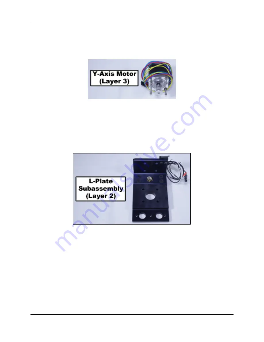
Remove y-axis motor and reinsert mounting hardware into the top of the motor.  Coil 
wire around base of motor and pass plug end under the coil to prevent from unraveling.  
Store y-axis motor in location as shown in Case Layer Drawing 3. 


28.


Remove four flat head screws that attach L-plate to the z-axis carriage.  Rotate lead 
screw to remove L-plate.  Replace flat head screws in z-axis carriage.  Coil z-axis limit 
switch wire and place plug end through coil to hold in place.  Store L-plate in location as 
shown in Case Layer Drawing 2.  


Содержание INVENT3D

Страница 1: ...INVENT3D Printer Kit Disassembly Instructions AST2 10 26 16 1 INVENT3D Printer Kit Disassembly Instructions Version 6 ...

Страница 2: ...bly should return the printer kit to the same condition in which it arrived Screws that are black anodized should not be removed II Case Layer Drawings The following Case Layer Drawings depict the layout and contents of each layer of components within the INVENT3D printer case These drawings are labeled from the top down within the case meaning Layer 1 is the top layer and Layer 4 is the bottom la...

Страница 3: ...INVENT3D Printer Kit Disassembly Instructions AST2 10 26 16 3 ...

Страница 4: ...INVENT3D Printer Kit Disassembly Instructions AST2 10 26 16 4 ...

Страница 5: ...ss for loading and unloading filament described in the INVENT3D Operating Instructions 2 Place the filament tube and USB cable into location as shown in Case Layer Drawing 3 3 Remove power supply and store in appropriate location as shown in Case Layer Drawing 3 The detachable cord can be stored when the second layer is placed on top ...

Страница 6: ...ide in location as shown in Case Layer Drawing 3 5 Remove white thumbscrews and spool holder from left side cover Store spool holder in location as shown in Case Layer Drawing 1 Place white thumbscrews in z axis and frame components box as shown in Case Layer Drawing 1 6 Remove top cover and store in location as shown in Case Layer Drawing 4 ...

Страница 7: ...ing pressure on the latch lightly with the pliers Straighten the latch if bent after removing Store zip ties in z axis and frame components box as shown in Case Layer Drawing 1 8 Remove wire sleeves Place wire sleeves in location as shown in Case Layer Drawing 3 9 Remove print board Store print board in location as shown in Case Layer Drawing 4 ...

Страница 8: ...plug breakout board clip Store rear cover in location as shown in Case Layer Drawing 4 Store power plug breakout board in location as shown in Case Layer Drawing 3 12 Remove black mini thumbscrew and HOT sign Store the HOT sign in plastic box for hot end components as shown in Case Layer Drawing 3 Store the black mini thumbscrew in the plastic box for x axis components as shown in Case Layer Drawi...

Страница 9: ... as shown in Case Layer Drawing 2 Place the front cover in the location as shown in Case Layer Drawing 4 15 Remove orange thumbscrews and RAMBo board from bottom frame plate Place the RAMBo board in the location as shown in Case Layer Drawing 1 with fan wiring coiled Store the orange thumbscrews in the plastic case for z axis and frame components as shown in Case Layer Drawing 1 ...

Страница 10: ...ox for x axis components shown in Case Layer Drawing 1 17 Remove the extruder motor from its seating on the extruder bottom Remove the filament drive from the extruder motor and replace the filament drive mounting hardware in the extruder motor Coil the extruder motor wire around the base of the motor and store in the location as shown in Case Layer Drawing 3 Store filament drive in location as sh...

Страница 11: ... on the extruder bottom to remove Only apply pressure to the upper portion of the hot end Coil wires and use a detachable zip tie to hold in place Store the hot end in plastic box for hot end components as shown in Case Layer Drawing 3 Store hot end component box in location shown in Case Layer Drawing 1 ...

Страница 12: ...t clamp longer screws should be inserted into the belt clamp Remove x axis limit switch from extruder bottom and re insert the screws into the limit switch with nuts on ends Coil limit switch wire and place in plastic box for x axis components as shown in Case Layer Drawing 1 Store extruder bottom in location as shown in Case Layer Drawing 1 the extruder bottom should be placed below the extruder ...

Страница 13: ... axis belt Remove z axis limit switch end stop with spring Remove yellow thumbscrew from z axis lock Place the idler bolt x axis belt z axis limit switch end stop with spring and yellow thumbscrew into the plastic case for x axis components shown in Case Layer Drawing 1 Store x axis component box in location shown in Case Layer Drawing 1 ...

Страница 14: ...base of motor Store the x axis motor in the location as shown in Case Layer Drawing 3 22 Remove lead screw knob by loosening set screw and set aside Remove top frame plate lifting the bearing from the lead screw at the same time Store flat head screws and bearing in plastic case for z axis and frame components as shown in Case Layer Drawing 1 Place top frame plate in location as shown in Case Laye...

Страница 15: ...ps from print board plate and reinsert mounting hardware into the print board plate Remove print board spacer and springs Place springs on red thumbscrews and reinsert into print board plate Place front and rear board clamps print board spacer and blue thumbscrew into the plastic case for y axis components as shown in Case Layer Drawing 1 Place print board plate in location as shown in Case Layer ...

Страница 16: ...t clamp in the locations from which they were removed Store diamond plate in plastic box for y axis components as shown in Case Layer Drawing 1 25 Remove front idler bolt located in slotted hole on y axis plate and replace nut on end Remove y axis belt Store idler bold and y axis belt in plastic case for y axis components as shown in Case Layer Drawing 1 ...

Страница 17: ...ts on ends Coil y axis limit switch wire and pass plug end through the coil so that it doesn t become unraveled Store idler bolts and flat head screws in plastic case for y axis components as shown in Case Layer Drawing 1 Place y axis components plastic box in location as shown in Case Layer Drawing 1 Place y axis plate in location as shown in Case Layer Drawing 3 ...

Страница 18: ...der the coil to prevent from unraveling Store y axis motor in location as shown in Case Layer Drawing 3 28 Remove four flat head screws that attach L plate to the z axis carriage Rotate lead screw to remove L plate Replace flat head screws in z axis carriage Coil z axis limit switch wire and place plug end through coil to hold in place Store L plate in location as shown in Case Layer Drawing 2 ...

Страница 19: ...t screw Store the z axis motor in location as shown in Case Layer Drawing 3 30 Remove green thumbscrews that attach printer legs to left and right side frames and remove printer legs Remove printer feet from printer legs and replace printer foot mounting hardware back into the printer feet Store green thumbscrews in plastic case for z axis and frame components as shown in Case Layer Drawing 1 Stor...

Страница 20: ...rom left and right side frames Store bottom frame plate in location as shown in Case Layer Drawing 2 Store flat head screws in plastic case for z axis and frame components as shown in Case Layer Drawing 1 Store z axis and frame components case in location as shown in Case Layer Drawing 1 ...

Страница 21: ...de channels on left and right side frames Insert black thumbscrews and tighten to attach side covers to side frames Be careful that the z axis carriage does not slide off of the rail Store left side assembly and right side assembly in locations as shown in Case Layer Drawing 2 ...

Страница 22: ...D Printer Kit Disassembly Instructions AST2 10 26 16 22 33 Compare the following photos of completed case layers with the layers of your printer case to ensure that all components are in their proper locations ...

Страница 23: ...INVENT3D Printer Kit Disassembly Instructions AST2 10 26 16 23 ...

Отзывы: