V2.4 03/08/18
TD0068
Page 21 of 38
This Document is uncontrolled when printed unless over stamped “CONTROLLED DOCUMENT”
5.
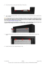
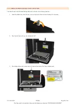
This will reveal three mounting points at the bottom of the system.
6.
Using a 10mm Nut Spinner/Ratchet, unscrew the two M6 nuts to remove the blank fascia and strengthener at the
top of the system.
NOTE:
If the cabinet is part of a system with additional extensions there will be an interface PCB located on
the back of the 1U strengthener with several cables connected to it. Carefully let the strengthener hang in
front of the first strip without disconnecting any cables. For more information on extension cabinets please
refer to the
If you are adding an extension cabinet to an existing system, an Interface PCB and chassis will have been
supplied for the existing cabinet and must be fitted as shown later in this document.
7.
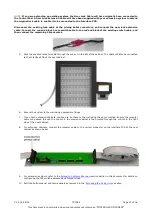
Removing the blank fascia and strengthener will reveal the second set of mounting points at the top of the
system.
8.
Repeat this section for any extension cabinets you have.

