V2.4 03/08/18
TD0068
Page 18 of 38
This Document is uncontrolled when printed unless over stamped “CONTROLLED DOCUMENT”
6.3
ROUTING CABLES
1.
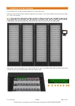
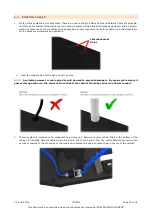
On top of the system are two knockouts. These are used to bring the Mains Cable and Network Cable (if applicable)
out through the cabinet to the mains spur and network socket. Using a large flat headed screwdriver and a hammer,
carefully knockout one or both of these holes depending on your requirements. Refer to Section 5.4 Wall Preparation
for the knockout dimensions and positions.
2.
Feed the mains cable out through one of the holes.
NOTE:
A suitable grommet or cable gland should be used to prevent damage to the mains cable where it
passes through the hole. The mains cable outside of the cabinet should be enclosed in 20mm conduit.
3.
If your system is intended to be connected to a Network, a Network coupler will be fitted in the bottom of the
cabinet. An existing Network cable will be in place to link to the Control Pod. The onsite Network connection can
now be connected to the other side of the coupler and passed through a knockout hole in the top of the cabinet.
20mm Knockout
Holes


