V2.4 03/08/18
TD0068
Page 23 of 38
This Document is uncontrolled when printed unless over stamped “CONTROLLED DOCUMENT”
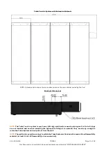
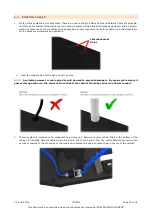
NOTE:
If you are extending an existing system, the Door Lock Cable will have originally been connected to
the Control Pod. A Door Lock Extension Cable will have been supplied with your extension system to extend
the original lock cable to enable it to be connected to the Interface PCB.
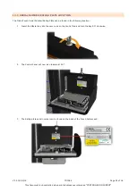
Disconnect the existing lock cable at the joining bullet connectors, and connect the new lock extension
cable. Connect the red and black 2 core switch cable to the red and black of the existing switch cable, and
then connect the remaining 2 black wires.
5.
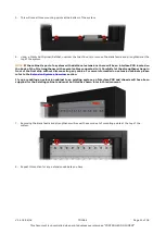
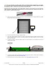
Pass the uncoiled receptor cable through the cut-out in the left of the cabinet. The cable will later be connected
to the Interface PCB of the next cabinet.
6.
Secure the system to the wall using appropriate fixings.
7.
If you have extension cabinets, continue to fix these to the wall using the same method. Ensure the receptor
cable you passed through the cut-out in the previous cabinet is then routed through the cut-out in the right
side of the next cabinet.
8.
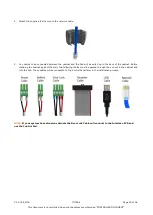
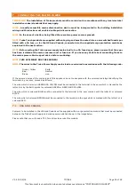
For extension cabinets, connect the receptor cable to the correct connector on the interface PCB of the next
cabinet as shown below.
9.
For extension systems, refer to the
section earlier in this document for details on
configuring the DIP switch addresses and Jumper Links.
10.
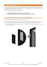
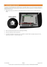
Refit the bottom panel and fascia panels as removed in the ‘
’ section.


