


1 8
1 8
1 8
1 8
1 8
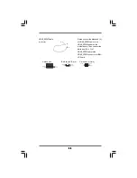
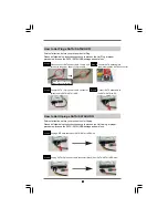
FLOPPY
1
Pin
1
the red-striped side to Pin1
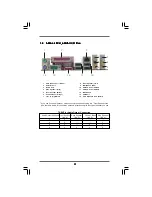
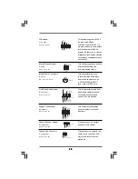
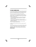
Primary IDE Connector (Blue)
Secondary IDE Connector (Black)
(39-pin IDE1, see p.10, No. 17)
(39-pin IDE2, see p.10, No. 18)
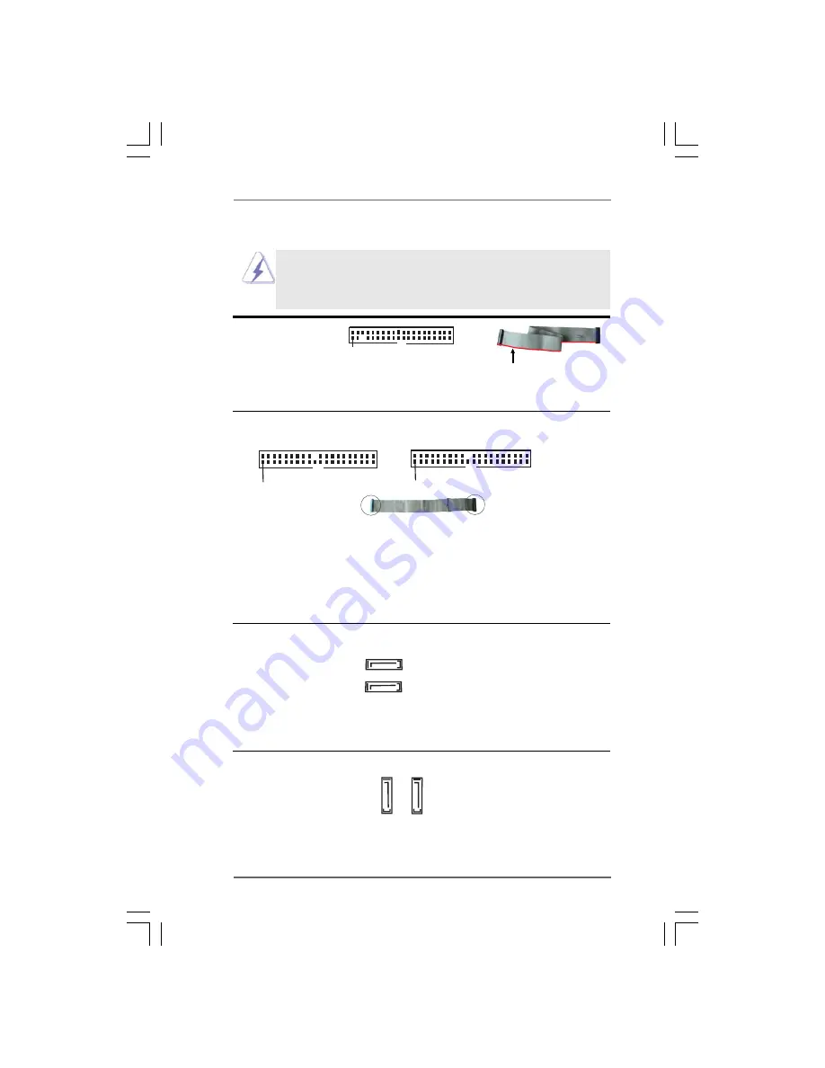
Serial ATA Connectors (Black)
These two Serial ATA (SATA)
(SATA1: see p.10, No. 13)
connectors are supported by
(SATA2: see p.10, No. 11)
NVIDIA
®
nForce3 250
southbridge, support SATA data
cables for internal storage
devices. The current SATA
interface allows up to 1.5 Gb/s
data transfer rate.
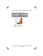
Serial ATAII Connectors
These two Serial ATAII (SATAII)
(SATA II_1, red: see p.10 No. 9)
connectors are supported by
(SATA II_2, orange: see p.10 No. 10)
JMicron
®
JMB363 (PCIE x1
interface), support SATA
data cables for internal storage
devices. The current SATAII
interface allows up to 3.0 Gb/s
data transfer rate.
SATA1
SATA2
SATAII_1
SATAII_2
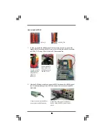
IDE
1
PIN1
IDE2
PIN1
connect the black end
to the IDE devices
connect the blue end
to the motherboard
80-conductor ATA 66/100/133 cable
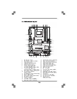
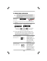
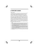
2.6 Onboard Headers and Connectors
2.6 Onboard Headers and Connectors
2.6 Onboard Headers and Connectors
2.6 Onboard Headers and Connectors
2.6 Onboard Headers and Connectors
Floppy Connector
(33-pin FLOPPY1)
(see p.10, No. 24)
Note: Make sure the red-striped side of the cable is plugged into Pin1 side of the
connector.
Onboard headers and connectors are NOT jumpers. Do NOT place
jumper caps over these headers and connectors. Placing jumper
caps over the headers and connectors will cause permanent dam-
age of the motherboard!
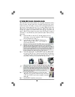
Note: If you use only one IDE device on this motherboard, please set the IDE
device as “Master”. Please refer to the instruction of your IDE device vendor
for the details. Besides, to optimize compatibility and performance, please
connect your hard disk drive to the primary IDE connector (IDE1, blue) and
CD-ROM to the secondary IDE connector (IDE2, black).


