16
17
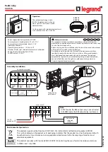
7. Mechanical mounting
The switching unit must be mounted correctly:
• In a dust-protected and moisture protected switch cabinet or casing.
• For use in an environment with contamination level 2.
• With a protection type of at least IP54.
• On a 35 mm DIN support rail according to EN 50 022 .
The switching unit must not be installed in the immediate vicinity of an intense heat source.
The switching unit can be installed in any position.
The unit must not be operated in areas with major temperature changes.
ELMON
rail
32-242
Safety Relais
English
If there is no fault alarm, the operating state is shown via the LED
Power
(on). When signalling a fault alarm
the number of pulses emitted indicates the nature of the fault:
Pulse Fault alarm
1
Supply voltage outside the available range
3
Output control
Stop Channel 1
faulty
4
Output control
Stop Channel 2
faulty
5
Data transfer between microcontrollers faulty
6
Error in testing signal input
(Channel 1 / Channel 2)
6.2
Connection terminals
Pin
1 2
(Not allocated)
Pin
3 11
Signal input
Channel 1
Pin
3 10
Signal input
Channel 2
Pin
4 5
Relay output to
Channel 1
control
Pin
6 7
Relay output to
Channel 2
control
Pin
8 9
Supply voltage 24 V AC/DC
8
7
6
5
4
9
10
3
2
1
11


