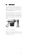
Furthermore the object plate can be done into
the base stand with either the black or white
side face-up according to the colour of the ob-
jects itself. Insert the stage springs, which will
later be used for fastening objects.
Please note: There might be other instructions
to assembly other bases or stands.
2.2.
Adjusting the Sharpness
The microscope can be adjusted so that a
sharp image at all levels of enlargement re-
sults.
You can achieve this in the following way:
The distance of the eyepieces has to be ad-
justed by screwing up the eyepiece cone (2) to
the individual interpupillary distance
Both dioptre rings has to be set to 0.
The highest magnification factor will be ad-
justed by the help of the magnification
changer, a stopper is clearly noticeable.
The picture will be focussed by the drive me-
chanism (10), whereas you have to look
through only one eyepiece. If that isn’t possi-
ble, the microscope body (4) has to move
along the column (11) till you see a picture,
clamp the body again. Following the picture
has to be focussed by the drive.
At least you have to choose the lowest magni-
fication factor and try to adjust the sharpness
by rotating the dedicated dioptre ring. Please
note: You don’t need to change the drive
knob!
After the microscope has been set, the object
being viewed will be sharply portrayed at all
levels of enlargement.
In case there are objects with different high,
then it is only necessary to focus the object
again (by changing the drive at highest magni-
fication factor).
A new readjustment is only necessary if an-
other person is using the microscope.
2.3.
General Operating Instructions
2.3.1.
Adjusting the Height of the Micro-
scope:
In general you can adjust the height with the
help of the slow –motion tangent screw. If this
doesn’t suffice push the unit to the column by
loosening the knurled knob on the back side of
the unit until the height is adjusted. Once this is
complete, retighten the knob. When doing this
watch out for the clamp ring (additional acces-
sories), which should prevent the unit from in-
advertently slipping. It should be reattached af-
ter the unit has been pushed.
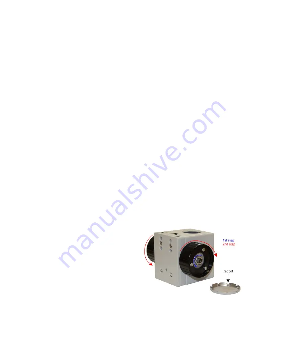
2.3.2. The
stiff motion of the drive
(drive
mechanism with ball-bearing slide 50mm) can
be changed by removing the gray lacquered
cap and by loosening the locknut.
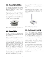
Picture 3:
Adjustment of the stiff motion at the drive 50
mm
10


