Содержание SharpSwitch PCIE-9205

Страница 1: ...SharpSwitch PCIE 9205 Installation and Use P N 6806800U18D March 2018 ...

Страница 2: ...ferenced in another document as a URL to an Artesyn website The text itself may not be published commercially in print or electronic form edited translated or otherwise altered without the permission of Artesyn It is possible that this publication may contain reference to or information about Artesyn products machines and programs programming or services that are not available in your country Such...

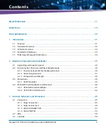
Страница 3: ...ng and Inspecting Card 35 2 2 Environmental Thermal and Power Requirements 36 2 2 1 Environmental and Thermal Requirements 36 2 2 2 Power Requirements 37 2 2 3 Dimensions and Weight 38 2 3 Precautions 38 2 3 1 ESD Prevention 39 2 4 PCIE 9205 Card Installation and Removal 40 2 4 1 PCIE 9205 Card Installation 41 2 4 2 PCIE 9205 Card Removal 42 3 Controls Indicators and Connectors 45 3 1 Connectors 4...

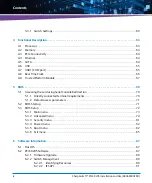
Страница 4: ...7 5 BIOS 69 5 1 Accessing the card using Serial Console Redirection 70 5 1 1 Directly connected terminal requirements 70 5 1 2 Default access parameters 71 5 2 BIOS Startup 71 5 3 BIOS Setup 72 5 3 1 Main menu 73 5 3 2 Advanced menu 74 5 3 3 Security menu 81 5 3 4 Power menu 82 5 3 5 Boot menu 82 5 3 6 Exit menu 85 6 Software Information 87 6 1 Host OS 87 6 2 PCIE 9205 Software 87 6 2 1 Firmware U...

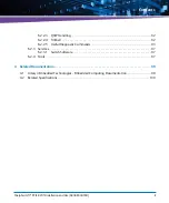
Страница 5: ... 2 2 3 QSFP Handling 92 6 2 2 4 fmShell 92 6 2 2 5 Useful Diagnostic Commands 93 6 2 3 Services 97 6 2 3 1 Switch Software 97 6 2 4 Tools 97 A Related Documentation 99 A 1 Artesyn Embedded Technologies Embedded Computing Documentation 99 A 2 Related Specifications 100 ...

Страница 6: ...SharpSwitch PCIE 9205 Installation and Use 6806800U18D 6 Contents ...

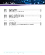
Страница 7: ...sions and Weight of PCIE 9205 card 38 Table 3 1 PCIE 9205 Card Edge Connector 1 Pinout 45 Table 3 2 PCIE 9205 Card Edge Connector 2 Pinout 49 Table 3 3 Micro USB UART port pinout 55 Table 3 4 Micro USB port pinout 55 Table 3 5 Faceplate LED 57 Table 3 6 Switch Settings 60 Table 6 1 mCPU Commands 89 Table 6 2 fmShell Commands 94 Table A 1 Artesyn Embedded Technologies Embedded Computing Publication...

Страница 8: ...SharpSwitch PCIE 9205 Installation and Use 6806800U18D 8 List of Tables ...

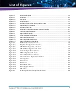
Страница 9: ...BIOS Setup Main menu 73 Figure 5 4 BIOS Setup Advanced menu 74 Figure 5 5 Boot Configuration sub menu 75 Figure 5 6 Platform Information sub menu 76 Figure 5 7 Peripheral Configuration sub menu 77 Figure 5 8 CPU SATA Configuration sub menu 77 Figure 5 9 CPU sSATA Configuration sub menu 78 Figure 5 10 Video Configuration sub menu 78 Figure 5 11 USB Configuration sub menu 79 Figure 5 12 Console Redi...

Страница 10: ...SharpSwitch PCIE 9205 Installation and Use 6806800U18D 10 List of Figures ...

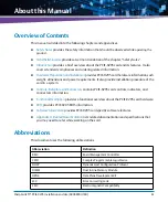
Страница 11: ... also provide installation procedure of the card in a system Controls Indicators and Connectors contains PCIE 9205 card controls indicators and connectors information Functional Description provides a functional overview about the PCIE 9205 card hardware BIOS provides PCIE 9205 BIOS information Software Information provides PCIE 9205 card specific software features Appendix A Related Documentation...

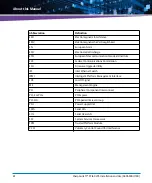
Страница 12: ...FCC Federal Communications Commission FCU Firmware Upgrade Utility IES Intel Ethernet Switch IPMI Intelligent Platform Management Interface LOS Loss Of Signal ME Management Engine PCI Peripheral Component Interconnect PCI E or PCIe PCI Express PCI SIG PCI Special Interest Group PSU Power Supply Unit SATA Serial ATA SOL Serial Over LAN SSF System Services Framework TPM Trusted Platform Module VCCI ...

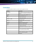
Страница 13: ...screenoutputandcoderelatedelements or commands in body text Courier Bold Used to characterize user input and to separate it from system output Reference Used for references and for table and figure descriptions File Exit Notation for selecting a submenu text Notation for variables and keys text Notation for software buttons to click on the screen and parameter description Repeated item for example...

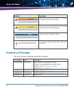
Страница 14: ...nor or moderate injury Indicates a property damage message No danger encountered Pay attention to important information Notation Description Part Number Date Description 6806800U18D March 2018 Restructured and reorganized the manual Added a note and updated screens in BIOS section Added a section Switch Settings on page 60 Updated Table 2 2 on page 37 6806800U18C April 2017 Updated the section BIO...

Страница 15: ...evelopment It must not be used in safety critical components life supporting devices or on aircraft Only personnel trained by Artesyn or persons qualified in electronics or electrical engineering areauthorizedtoinstall removeormaintaintheproduct Theinformationgiveninthismanual is meant to complete the knowledge of a specialist and must not be used as replacement for qualified personnel Keep away f...

Страница 16: ...tic discharge Make sure that each of the system s parts contact the EMI gasket The system contains gaskets at the shelf and module level The shelf is also fitted with ESD snaps for the use with conductive wrist straps Please take care for proper ESD protection of the operator This is a Class A product based on the standard of the Voluntary Control Council for Interference by Information Technology...

Страница 17: ...ap or ESD shoes Hold the product by its edges and do not touch any components or circuits Damage of System or Card Installing a card in the wrong slot may cause card or system damage Only install PCIE cards in the designated slots Removing the card from the system while the system is powered up may damage the card Whenever removing the card from the system power down system first This does not app...

Страница 18: ...IE cards or filler cards Product Damage High humidity and condensation on card surfaces causes short circuits Do not operate the system outside the specified environmental limits Make sure the system is completelydryandthereisnomoistureonanysurfacebeforeapplyingpower Donotstartthe system below 0 0C Injuries or Short Circuits To avoid damage or injuries always check that there is no more voltage on...

Страница 19: ...ity Cabling Personal Injury The cabling should follow existing cable paths using existing or similar cable fastenings Never change the system s cabling as delivered by Artesyn Check proper function of the system after cabling extensions To avoid injuries always ensure that cables are securely installed so that nobody can trip over them Personal Injury through Electric Shock Touching contacts and c...

Страница 20: ...ules which are fully certified and which meet all relevant safety standards Personal Injury Optical QSFP modules may be classified as laser products When installing and using any of these QSFP modules the regulations which correspond to the respective laser class apply to the whole PCIE card Not complying to these regulations may lead to personal injury When installing and using optical QSFP modul...

Страница 21: ... Installation and Use 6806800U18D 21 Environment Environmental Damage Improperly disposing of used products may harm the environment Always dispose of used products according to your country s legislation and manufacturer s instructions ...

Страница 22: ...SharpSwitch PCIE 9205 Installation and Use 6806800U18D Safety Notes 22 ...

Страница 23: ...lle von Artesyn Das System erfüllt die für die Industrie geforderten Sicherheitsvorschriften und darf ausschließlich für Anwendungen in der Telekommunikationsindustrie im Zusammenhang mit Industriesteuerungen und in der Entwicklung verwendet werden Es darf nicht in sicherheitskritischen Anwendungen lebenserhaltenden Geräten oder in Flugzeugen verwendet werden Einbau Wartung und Betrieb dürfen nur ...

Страница 24: ...ng vorhanden ist Die PCIE Karten müssen mit der Frontblende installiert und alle freien Steckplätze müssen mit Blindblenden abgedeckt sein Erdung Wenn das Produkt nicht richtig geerdet ist kann es es durch elektrostatische Entladungen beschädigt werden Stellen Sie sicher dass alle Systemteile die EMV Dichtung berühren Die Dichtungen befinden sich sowohl am System als auch an den einzelnen Modulen ...

Страница 25: ... von Einsteckkarten Produktschaden Berühren Sie das Karte oder elektrische Komponenten ohne ausreichenden ESD Schutz kann dies zu einer Beschädigung des Karten führen Bevor Sie Karten berühren vergewissern Sie sich dass Sie in einem ESD geschützten Bereich arbeiten oder tragen Sie ein ESD Handgelenkband oder ESD Schuhe Fassen Sie Karten nur an der Seite an und berühren Sie keine elektronischen Kom...

Страница 26: ...n Sie die Frischluftzufuhröffnung an der Vorderseite des Systems völlig frei und stellen Sie sicher dass sich die Frischluft nicht mit der Abluft von anderen Systemen mischt Um eine ungestörte Luftzirkulation zu gewährleisten stellen Sie sicher dass alle Steckplätze mit PCIE Karten oder Platzhaltern belegt sind Beschädigung des Systems Durch hohe Luftfeuchtigkeit können Kurzschlüsse entstehen Betr...

Страница 27: ... bei der Arbeit mit dem System keine metallischen Gegenstände an Ihren Händen oder Armen und lassen sie keine metallischen Gegenstände um Ihren Hals hängen Seien Sie extrem vorsichtig mit elektrisch leitenden Werkzeugen und Gegenständen in der Nähe der PSUs Beschädigung des Products Falscher Anschluss von Stromkabeln kann das Product beschädigen Achten Sie darauf dass Sie das Stromkabel mit der ri...

Страница 28: ...el beschädigt werden und der Datentransfer nicht mehr stattfinden Stellen Sie sicher dass Kabel nicht geknickt werden USB Die nachfolgend aufgeführten Schnittstellen sind Wartungsschnittstellen USB1 USB2 und Console Während des Normalbetriebs darf an diesen Schnittstellen kein Kabel angeschlossen sein Im Wartungsfall angeschlossene Kabel dürfen eine Länge von 3m nicht überschreiten QSFP Modules Ge...

Страница 29: ...en werden Verletzungsgefahr der Augen Optische QSFP Module können Laserstrahlen aussenden wenn kein Kabel angeschlossen ist Blicken Sie daher nicht direkt in die Öffnung eines QSFP Moduls um Verletzungen der Augen zu vermeiden Beschädigung von QSFP Modulen Die Schutzkappe eines QSFP Modules dient dazu die sensible Optik des QSFP Modules gegen Staub und Schmutz zu schützen Entfernen Sie die Schutzk...

Страница 30: ...SharpSwitch PCIE 9205 Installation and Use 6806800U18D Sicherheitshinweise 30 ...

Страница 31: ...be offloaded to the switch silicon before the packet even gets distributed into the low latency PCI Express infrastructure PCI I O virtualization functions allow for each virtual function VF on each of the installed microserver cards to have direct and sole access to one or multiple virtual Ethernet network interface controllers The integrated switch and Ethernet controller allows for hardware bas...

Страница 32: ... C1985 2 2 R647 R651 C562 R1655 C1980 L14 U47 R648 R652 R1309 R1658 R1888 R1659 R1660 R653 C564 R650 C565 R656 C1989 C1978 C1990 R1556 C371 C369 C373 R654 C376 Q6 U46 C1988 C1981 R1559 R1558 C2313 C2325 R354 R353 C1993 C1979 C2319 R2023 C473 C1229 12 7 C2327 C2326 C572 C2335 C2308 C420 C1239 6 C2307 C1240 C1241 C470 R433 C465 U48 R1056 R425 C464 Q19 R1653 R1652 C1998 C415 C467 C898 C900 C570 E4 C4...

Страница 33: ... FCC 15 109 b 2015 Class A ANSI C63 4 2003 FCC 15 109 g CISPR 22 1997 2003 Class A ANSI C63 4 2003 ICES 003 Issue 5 2012 Class A CAN CSA CISPR 22 2008 Radiated Emissions CISPR 22 2012 Class A CISPR 22 2012 EN 300 386 V1 6 1 2012 Class A EN 55022 2011 FCC 15 107 2015 Class A ANSI C63 4 2003 ICES 003 Issue 5 2012 Class A CAN CSA CISPR 22 2008 Conducted Emissions EN 300 386 v1 6 1 2012 EN 61000 4 2 2...

Страница 34: ...ber given in the following table when ordering a card supported software packages or requesting support information Consult your local Artesyn sales representative for more information Table 1 2 Ordering Information Part Number Description PCIE 9205 SharpSwitch card 1x Intel FM10840 1x 8 core Intel Xeon D 1541 32 GB ECC DDR4 ...

Страница 35: ...nspection To inspect the shipment perform the following steps 1 Verify that you have received all items of your shipment One SharpSwitch PCIE 9205 card One printed copy of Quick Start Guide One printed copy of Safety Notes Summary Any optional items ordered 2 Check your shipment and report any damage or differences to the Contact Center at RMASupport ec Artesyn com Damage of Circuits Electrostatic...

Страница 36: ...uirements Make sure the card is thoroughly inspected before shipment If any damage has occurred during transportation please contact our Contact Center immediately Operating temperatures refer to the temperature of the incoming air passing across the card and out of the faceplate and not the temperature of the components Card Damage High humidity and condensation on the card surface causes short c...

Страница 37: ...o 70 C Minimum Airflow Reference to sea level 500 LFM 2 5 m sec 400 LFM 2 m sec for 35 C Operation Temperature Change 30 C hr 30 C hr Relative Humidity 5 to 85 Non Condensing 5 to 90 Non Condensing but not to exceed 0 024 kg of water per kg of dry air Shock and Vibration 0 1G s 5 to 200Hz EN 300 019 2 2 Class 2 3 Altitude Up to 1800m With 40 C operation between 1800m and 4000m Up to 12000m Table 2...

Страница 38: ...d Weight of PCIE 9205 card Component Dimensions l x w x h in mm Weight in Kg PCIE 9205 335 x 128 x 25 0 570 To reduce the risk of personal injury fire or damage to the equipment do not overload the AC supply circuit that provides power to the chassis The card must be powered and connected only to a controlled voltage source To avoid shock make sure that the power cables are connected to a properly...

Страница 39: ...ricity around you Do not touch the solder point pin or bare circuit Do not leave the device in the place where others can operate it Electrostatic Discharge Do not touch the circuit with bare hands The static electricity of the human body may damage the ElectroStatic Sensitive Devices ESSDs on the circuit Make sure that you wear an ElectroStatic Discharge ESD preventive wrist strap or antistatic g...

Страница 40: ...charge and incorrect module installation and removal can damage circuits or shorten their life Before touching the module or electronic components make sure that you are working in an ESD safe environment Shipping the card along with a server is not recommended If you still need to ship the card along with the server ensure the card is properly secured in the server Check if necessary precautions ...

Страница 41: ...hether the host system has the required PCIe slot with a minimum x4 PCIe connector to hold the card 4 Insert the PCIE 9205 card into the PCIe slot secure it and ensure that the card is properly fitted in the PCIe slot 5 Lock the slot ejectors close the system cover and then power on the system For detailed information about the PCIe card installation refer to respective rack mount server manufactu...

Страница 42: ...uct Damage Do not attempt to insert and operate the PCIE 9205 card in any other system other than the Artesyn MaxCore system This may not only damage the PCIE 9205 card but also the system the card is plugged into Although the PCIE 9205 card looks similar to a standard PCI Express card it is not a standard PCIe compliant product In the MaxCore platform a PCIE 9205 card placed in slot 1 or slot 15a...

Страница 43: ...Installation SharpSwitch PCIE 9205 Installation and Use 6806800U18D 43 4 Gently pull the PCIE 9205 card from the slot 5 Close the cover of the system Place the PCIE 9205 card into an ESD protective bag and seal it appropriately ...

Страница 44: ...Hardware Preparation and Installation SharpSwitch PCIE 9205 Installation and Use 6806800U18D 44 ...

Страница 45: ...e Connector 1 This section provides information about the PCIE 9205 card edge connector 1 pinout Figure 3 1 Faceplate User LED COM0 Via USB USB P0 100G Ethernet QSFP28 P1 100G Ethernet QSFP28 Reset Button Dual in line Package DIP switches SW100 SW101 SW200 on the back of the board are for debug purpose only Their default settings are off Table 3 1 PCIE 9205 Card Edge Connector 1 Pinout Pin Name Si...

Страница 46: ...3V AUX 3 3 Volt auxiliary power 3 3V 3 3 Volt power 11 WAKE Signal for Link reactivation PRST Reset Mechanical Key 12 RSVD Reserved GND Ground 13 GND Ground REFCLK Reference clock 14 Tx_P 0 Transmitter Lane 0 REFCLK Differential pair 15 Tx_N 0 Differential pair GND Ground 16 GND Ground Rx_P 0 Receiver Lane 0 17 PRSNT2 Hot Plug presence detect Rx_N 0 Differential pair 18 GND Ground GND Ground 19 Tx...

Страница 47: ...ir GND Ground 35 GND Ground Rx_P 4 Receiver Lane 4 36 GND Ground Rx_N 4 Differential pair 37 Tx_P 5 Transmitter Lane 5 GND Ground 38 Tx_N 5 Differential pair GND Ground 39 GND Ground Rx_P 5 Receiver Lane 5 40 GND Ground Rx_N 5 Differential pair 41 Tx_P 6 Transmitter Lane 6 GND Ground 42 Tx_N 6 Differential pair GND Ground 43 GND Ground Rx_P 6 Receiver Lane 6 44 GND Ground Rx_N 6 Differential pair ...

Страница 48: ...ane 10 61 GND Ground Rx_N 10 Differential pair 62 Tx_P 11 Transmitter Lane 11 GND Ground 63 Tx_N 11 Differential pair GND Ground 64 GND Ground Rx_P 11 Receiver Lane 11 65 GND Ground Rx_N 11 Differential pair 66 Tx_P 12 Transmitter Lane 12 GND Ground 67 Tx_N 12 Differential pair GND Ground 68 GND Ground Rx_P 12 Receiver Lane 12 69 GND Ground Rx_N 12 Differential pair 70 Tx_P 13 Transmitter Lane 13 ...

Страница 49: ..._P 15 Receiver Lane 15 81 PRSNT 2 Hot plug present detect Rx_N 14 Differential pair 82 RSVD 2 Reserved GND Ground Table 3 1 PCIE 9205 Card Edge Connector 1 Pinout continued Pin Name Side B Description Name Side A Description Table 3 2 PCIE 9205 Card Edge Connector 2 Pinout Pin Name Side B Description Name Side A Description 1 12V 12 Volt power 12V 12 Volt power 2 12V 12 Volt power 12V 12 Volt powe...

Страница 50: ... Reserved GND Ground 13 GND Ground CPU1_UAR T1_TXD UART1 to CPU1 transmitter 14 GND Ground CPU1_UAR T1_RXD UART1 to CPU1 receiver 15 RSVD 2 Reserved GND Ground 16 RSVD 2 Reserved GND Ground 17 GND Ground CPU1_USB 2_BMC_DP USB port to CPU1 18 GND Ground CPU1_USB 2_BMC_D M USB port to CPU1 19 CPU1_GE 1_EXT_R X_D_P Gigabit Ethernet port to CPU1 Receiver Diff pair GND Ground 20 CPU1_GE 1_EXT_R X_D_M G...

Страница 51: ...25 GND Ground CPU1_GE0 _EXT_TX_ D_P GigabitEthernetporttoCPU1 transmitter Diff pair 26 GND Ground CPU1_GE0 _EXT_TX_ D_M 27 CPU1_CL K_100M _REFCLK _DP Reference Clock to CPU1 GND Ground 28 CPU1_CL K_100M _REFCLK _DN Differential pair GND Ground 29 GND Ground CPU1_100 M_REFCLK_ DP Reference Clock to CPU1 30 GND Ground CPU1_100 M_REFCLK_ DN Differential pair 31 NC Not connected GND Ground 32 NC Not c...

Страница 52: ...nnected NC Not connected 42 NC Not connected NC Not connected 43 NC Not connected GND Ground 44 GND Ground NC Not connected 45 CPU1_LP C_LAD0 LPC Port to CPU1 bus GND Ground 46 CPU1_LP C_LAD1 CPU1_LPC_ LFRAME_N LPC Frame to CPU1 47 CPU1_LP C_LAD2 CPU1_SERI RQ LPC Interrupt signal 48 CPU1_LP C_LAD3 PCH_SKL1_ PLTRST_N LPC reset signal 49 GND Ground GND Ground 50 NC Not connected CPU1_CLK OUT_LPC0 LP...

Страница 53: ...A3_RX_ D_M GND Ground 60 GND Ground CPU1_SATA 3_TX_D_P SATA3 port to CPU1 Transmitter Diff pair 61 GND Ground CPU1_SATA 3_TX_D_M 62 CPU1_SA TA2_RX_ D_P SATA2 port to CPU1 Receiver Diff pair GND Ground 63 CPU1_SA TA2_RX_ D_M GND Ground 64 GND Ground CPU1_SATA 2_TX_D_P SATA0 port to CPU1 Transmitter Diff pair 65 GND Ground CPU1_SATA 2_TX_D_M 66 CPU1_P2 E_EXT_R X_D_P PCIe to CPU1 Receiver Diff pair G...

Страница 54: ... to CPU1 Transmitter Diff pair 73 GND Ground CPU1_SATA 1_TX_D_M 74 CPU1_SA TA0_RX_ D_P SATA0 port to CPU1 Receiver Diff pair GND Ground 75 CPU1_SA TA0_RX_ D_M GND Ground 76 GND Ground CPU1_SATA 0_TX_D_P SATA0 port to CPU1 Transmitter Diff pair 77 GND Ground CPU1_SATA 0_TX_D_M 78 RRC 10G_P RRC_10G_EXT_RX_P GND Ground 79 RRC 10G_N RRC_10G_EXT_RX_N GND Ground 80 GND Ground RRC 10G_P RRC_10G_EXT_TX_P ...

Страница 55: ...e 3 1 4 MicroUSB Port The micro USB port is the USB 1 port of the CPU 82 CON_MN GR_PRSN T_N Management signal GND Ground Table 3 2 PCIE 9205 Card Edge Connector 2 Pinout continued Pin Name Side B Description Name Side A Description Table 3 3 Micro USB UART port pinout Pin Name 1 VBUS 2 Data 3 Data 4 Identification 5 GND Table 3 4 Micro USB port pinout Pin Name 1 VCC 5V 2 Data 3 Data 4 Identificati...

Страница 56: ...R1665 C137 R1306 C1097 D12 K R1322 R1323 R181 R582 C1131 R584 U42 C1227 D10 K R600 R1321 R474 R424 C2311 R1557 U41 R643 E53 R359 C386 C1969 C1971 R1887 7 12 D9 K R1320 R439 R200 R366 C270 C202 R254 R450 U118 C383 R1651 R1644 C1977 31 21 C1976 C1992 C1991 K C384 C377 R1642 C1967 R1643 C1968 R1645 C1972 R1656 C1975 R1657 C1982 C1984 C569 R658 R356 C1970 C1973 11 R1654 R1692 R1793 R1782 C2160 R1777 R...

Страница 57: ...4 Q19 R1653 R1652 C1998 C415 C467 C898 C900 C570 E4 C462 C1986 R1665 C137 R1306 C1097 D12 K R1322 R1323 R181 R582 C1131 R584 U42 C1227 D10 K R600 R1321 R474 R424 C2311 R1557 U41 R643 E53 R359 C386 C1969 C1971 R1887 7 12 D9 K R1320 R439 R200 R366 C270 C202 R254 R450 U118 C383 R1651 R1644 C1977 31 21 C1976 C1992 C1991 K C384 C377 R1642 C1967 R1643 C1968 R1645 C1972 R1656 C1975 R1657 C1982 C1984 C569...

Страница 58: ...C1986 R1665 C137 R1306 C1097 D12 K R1322 R1323 R181 R582 C1131 R584 U42 C1227 D10 K R600 R1321 R474 R424 C2311 R1557 U41 R643 E53 R359 C386 C1969 C1971 R1887 7 12 D9 K R1320 R439 R200 R366 C270 C202 R254 R450 U118 C383 R1651 R1644 C1977 31 21 C1976 C1992 C1991 K C384 C377 R1642 C1967 R1643 C1968 R1645 C1972 R1656 C1975 R1657 C1982 C1984 C569 R658 R356 C1970 C1973 11 R1654 R1692 R1793 R1782 C2160 R...

Страница 59: ... R433 C465 U48 R1056 R425 C464 Q19 R1653 R1652 C1998 C415 C467 C898 C900 C570 E4 C462 C1986 R1665 C137 R1306 C1097 D12 K R1322 R1323 R181 R582 C1131 R584 U42 C1227 D10 K R600 R1321 R474 R424 C2311 R1557 U41 R643 E53 R359 C386 C1969 C1971 R1887 7 12 D9 K R1320 R439 R200 R366 C270 C202 R254 R450 U118 C383 R1651 R1644 C1977 31 21 C1976 C1992 C1991 K C384 C377 R1642 C1967 R1643 C1968 R1645 C1972 R1656...

Страница 60: ...re IPC and MaxCore Micro systems The following figure shows SW100 switch location Figure 3 6 Location of SW100 Table 3 6 Switch Settings Switch MaxCore IPC MC1000 MaxCore Micro MC1500 SW100 1 OFF Down side position ON Up side position SW100 2 OFF Down side position OFF Down side position SW100 3 OFF Down side position OFF Down side position SW100 4 OFF Down side position OFF Down side position ...

Страница 61: ...ors SharpSwitch PCIE 9205 Installation and Use 6806800U18D 61 The black box on the upside indicates ON and on the downside indicates OFF Figure 3 7 MaxCore IPC and MaxCore Micro Switch Settings MaxCore IPC MC1000 MaxCore Micro MC1500 ...

Страница 62: ...Controls Indicators and Connectors SharpSwitch PCIE 9205 Installation and Use 6806800U18D 62 ...

Страница 63: ... The PCIE 9205 card contains one Intel Xeon Processor D also known as Broadwell DE SoC processor and an Intel FM10840 also known as RedRock Canyon NIC Switch 4 2 Memory The processor can be equipped with up to four DDR4 SO DIMMs two per Memory channel Depending on the available SO DIMM memory capacities this may result in a maximum memory capacity of 64GByte DDR4 memory per processor Figure 4 1 PC...

Страница 64: ...MaxCore MC3000 platform through one PCIe x1 Gen2 interface 4 4 Ethernet The processor on the PCIE 9205 may connect to an optional Ethernet Switch within the MaxCore system through a one Gigabit Ethernet interface Port0 and Port1 These connections are through the Xeon Processor D s integrated KR PHY and are configured for 1000BASE KX mode 1Gbps 1lane The FM10840 has two 100G Ethernet Interfaces P0 ...

Страница 65: ...a function USB2 0 Port3 is available only if the PCIE 9205 is operated in slot 1 or slot 15 of the MC3000 system In this case it may be configured to connect to the IO Panel of the system and provides a respective USB port on the IO panel USB3 0 Port1 is available for the CPU through a USB3 0 compatible connector same connector as used for USB2 0 Port1 at the PCIE 9205 faceplate as a regular USB p...

Страница 66: ...x driver is available at http www silabs com products mcu Pages USBtoUARTBridgeVCPDrivers aspx For a Windows host to access the COM ports of the CPU through the USB terminal port it needs to install the Silicon Laboratories silabenm Dual CP210x driver Two new COM ports will show up in the Device Manager CPU always uses Enhanced COM port 4 8 Real Time Clock The CPU on the PCIE 9205 card is provided...

Страница 67: ...pSwitch PCIE 9205 Installation and Use 6806800U18D 67 4 9 Trusted Platform Module A Trusted Platform Module TPM 1 2 compliant device is provided for the CPU on the PCIE 9205 and the device used is the Infineon SLB9660VQ1 2 FW4 40 ...

Страница 68: ...Functional Description SharpSwitch PCIE 9205 Installation and Use 6806800U18D 68 ...

Страница 69: ...nts The following are the main features of BIOS Initialization of the CPU build in CPU and memory Initialization of the PCI devices Setup utility for configuration data BMC support over IPMI Serial console redirection to a local port and Serial over LAN SOL Boot of Operation System The BIOS complies with the following specifications UEFI Specification 2 4 Plug and Play BIOS Specification 1 0a PCI ...

Страница 70: ...card s firmware provides a Serial Console Redirection feature allowing access to the card through a terminal directly connected to the card s serial interface and through the BMC via Serial over LAN feature The terminal can be connected to display text information Terminal keyboard input is redirected and treated as a normal PC keyboard input There is an appropriate BIOS Setup menu for configurati...

Страница 71: ...llowing are the default settings for serial redirection connection Terminal Type VT 100 Baud Rate 38400 Data Bits 8 Parity None Stop Bits 1 Flow Control No 5 2 BIOS Startup After power on or CPU reset the BIOS starts and displays the following banner on the console screen Figure 5 1 BIOS Console Screen ...

Страница 72: ...al key on the keyboard to enter BIOS Setup 5 3 BIOS Setup The BIOS Setup is an interactive interface to display and configure the BIOS parameters It is organized as set of menus sub menus and option items corresponding to the parameters Figure 5 2 After Hardware Initialization You can navigate through BIOS Setup by pressing arrow keys and you can enter or exit the sub menus by pressing Enter and E...

Страница 73: ...u Initially the Main menu is displayed on the BIOS Setup Utility screen as shown in the following figure The Main menu shows the BIOS version processor and memory information It allows you to change the system date and time displayed on the screen Figure 5 3 BIOS Setup Main menu ...

Страница 74: ...re organized in the form of sub menus The sub menus are labeled with symbol Using vertical arrow keys on the keyboard you can navigate to the required sub menu and enter into it by pressing Enter key on the keyboard To return one level back press Esc key For more information refer to the shortcut keys provided at the bottom of the screen Figure 5 4 BIOS Setup Advanced menu ...

Страница 75: ...BIOS SharpSwitch PCIE 9205 Installation and Use 6806800U18D 75 The following figure shows the content of Boot Configuration sub menu Figure 5 5 Boot Configuration sub menu ...

Страница 76: ...and Use 6806800U18D 76 The following figure shows the content of Platform Information sub menu It shows the card type PlatformBoardType thechipsettypeandsteppinginformationabouttheManagement Engine ME Figure 5 6 Platform Information sub menu ...

Страница 77: ... The following figure shows the Peripheral Configuration sub menu screen ThefollowingfigureshowstheCPUSATAConfigurationsub menu whichshowstheChipset s SATA controller settings Figure 5 7 Peripheral Configuration sub menu Figure 5 8 CPU SATA Configuration sub menu ...

Страница 78: ...he following figure shows the CPU sSATA Configuration sub menu which shows the Chipset s sSATA controller settings The following figure shows the Video Configuration sub menu screen Figure 5 9 CPU sSATA Configuration sub menu Figure 5 10 Video Configuration sub menu ...

Страница 79: ... this case the default Display Mode value on this card has to be changed to any alternative one The following figure shows the USB Configuration sub menu screen The Console Redirection sub menu shown below represents various available settings for console redirection feature There are global settings usually used for both COMA and COMB ports They can be overridden using settings in appropriate por...

Страница 80: ...ion and Use 6806800U18D 80 The Advanced menu has Expert View option Enabling this option displays additional sub menus as shown in the following figure Figure 5 12 Console Redirection sub menu Figure 5 13 Advanced menu Expert View enabled ...

Страница 81: ...800U18D 81 A detailed description of additional sub menus is not in the scope of this document 5 3 3 Security menu The Security menu displays security relevant information and changeable options including the Supervisor Password Figure 5 14 Security menu ...

Страница 82: ...enu The Power menu collects options allowing under particular circumstances to reduce power consumption 5 3 5 Boot menu TheBootmenurepresentsoptionsthatinfluencetheBIOSbehaviorregardingtheinitialization and utilization for subsequent Operating System boot Figure 5 15 Power menu ...

Страница 83: ...ecidewhetherUEFIorLegacybootdeviceshavetobetriedforbootingfirst Once UEFI Network Stack is enabled you can enable the PXE boot capability The Timeout option defines how long the BIOS pauses for a keystroke after the prompt Press Fn to Enter is displayed before it starts booting OS The EFI sub menu collects all UEFI boot options and allows to rearrange the order in which they are tried Figure 5 16 ...

Страница 84: ... and Use 6806800U18D 84 The Legacy sub menu allows you to organize all legacy options in a single plain list or according to their types Normal case as shown in the figure below Figure 5 17 Boot EFI Sub menu Figure 5 18 Boot Legacy Sub menu ...

Страница 85: ...ion and Use 6806800U18D 85 5 3 6 Exit menu The Exit menu provides various options such as saving or discarding changes and loading different sets of default settings Those options can be seen in the following figure Figure 5 19 Exit menu ...

Страница 86: ...BIOS SharpSwitch PCIE 9205 Installation and Use 6806800U18D 86 ...

Страница 87: ...ssigned requires a standard network driver for the FM10840 not specific to the PCIE 9205 card Under Linux this driver is named fm10k and it is capable to operate both physical and virtual functions 6 2 PCIE 9205 Software The PCIE 9205 card comes pre installed with CentOS 7 3 and various additional packages The following are Artesyn specific extensions Firmware update utilities Access utilities to ...

Страница 88: ...ond is the CPLD For more information on how to perform firmware upgrade refer to MaxCore MC3000 Platform Software Installation and Use manual 6 2 2 Switch Management This section provides a brief overview about Switch management Figure 6 1 Switching Software Components Overview Switch Software fm10k NIC driver UIO Module API fm10ks module Netlink API Boardctrl driver Intel IES Libraries FM10K Swit...

Страница 89: ...of 64GBit sec It can be used as regular network interface The PCIe Gen2 x 1 connection of PEP8 It is used by the switch management software IES to operate the switch itself and cannot be used for network traffic 6 2 2 1 Identifying Resources In the MaxCore environment PEP0 to PEP3 are visible as NICs from the active management CPU mCPU The naming of the network interfaces depends on various circum...

Страница 90: ... device 1 func 1 vendor 0x8086 device 0x15a4 class 0x20000 pci location mcpu 3c 00 0 plx switch 1 plx station 3 plx port 12 slot 11 device 2 func 1 vendor 0x8086 device 0x15a4 class 0x20000 pci location mcpu 3e 00 0 plx switch 1 plx station 3 plx port 13 slot 11 device 3 func 1 vendor 0x8086 device 0x15a4 class 0x20000 pci location mcpu 40 00 0 plx switch 1 plx station 3 plx port 14 slot 11 device...

Страница 91: ...ernet Switch IES is an API which abstracts the fm10k switch capabilities It is mainly used on PCIE 9205 by the Switch Software which provides switch management service for the MaxCore SSF The IES library supports sharing switch hardware and the IES library context over several processes One process is the IES master performing the initial setup of the library and the switch hardware Other processe...

Страница 92: ...obtain status and diagnostic information It should not be used to alter switch configuration because this may conflict with the running switch management process SSF agent The following section contains the list of commands in fmShell To display help use the command fmShell h To start fmShell interactively as IES client Ctrl C or Ctrl D to exit use the command fmShell iLs Alternatively call the fm...

Страница 93: ...ompletion For general help on the expression syntax check help in the command prompt For specific help on PCIE 9205 IES specific functions and commands check toolHelp 6 2 2 5 Useful Diagnostic Commands Most of the features provided by the following commands are provided via SSF fmShell can be used to quickly obtain the information when logged into the PCIE 9205 card These commands can either be ca...

Страница 94: ... 100G 1 FM_PORT_MODE_ADMIN_PWRDOWN FM_PORT_STATE_DOWN 2 QSFP1 DOWN 0G 1 FM_PORT_MODE_ADMIN_PWRDOWN FM_PORT_STATE_DOWN 3 QSFP1 DOWN 0G 1 FM_PORT_MODE_ADMIN_PWRDOWN FM_PORT_STATE_DOWN 4 QSFP1 DOWN 0G 1 FM_PORT_MODE_ADMIN_PWRDOWN FM_PORT_STATE_DOWN 5 QSFP2 UP 100G 1 FM_PORT_MODE_ADMIN_PWRDOWN FM_PORT_STATE_DOWN 6 QSFP2 DOWN 0G 1 FM_PORT_MODE_ADMIN_PWRDOWN FM_PORT_STATE_DOWN 7 QSFP2 DOWN 0G 1 FM_PORT_...

Страница 95: ...ows all counters of a port otherwise only those that have changed since the previous call filter string can be one of E D or a combination to list only ingress egress error or drop counters respectively Example fmShell bdPortCountShow 0 1 E 0 PEP8 RxFCSErrors E 0 0 0 sec 0 PEP8 RxSymbolErrors E 0 0 0 sec 0 PEP8 RxFrameSizeErrors E 0 0 0 sec 0 PEP8 RxFramingErrorPkts E 0 0 0 sec 0 PEP8 RxFCSErrorsO...

Страница 96: ...28 0x11 Connector Type 02 No separable connector 0x23 Spec Comp 03 Extended Ext Spec Comp 40 100G AOC Active Optical Cable Length 12 5m VendorName 14 FINISAR CORP VendorOUI 25 0x009065 e VendorPN 28 FCBN425QB1C05 VendorRev 38 A1 CC_Base 3f b5 Calculated b5 VendorSN 44 DTP01VK DateCode 54 150605 CC_EXT 5f cf Calculated cf Lower Memory Map LOS 03 RX1 RX2 RX3 RX4 TX1 TX2 TX3 TX4 FAULT 04 Temperature ...

Страница 97: ...tl This service is started at the boot time and it is always expected to be active and running for managing switch 6 2 4 Tools This section provides PCIE 9205 MaxCore specific software are installed in opt bladeservices The following are contents in this directory bin directory fmClient Wrapper for fmShell to start interactive IES client shell fmMaster Wrapper for fmShell to start interactive IES ...

Страница 98: ...CIE 9205 Installation and Use 6806800U18D 98 lib directory libFocalpointSDK libLTStdPlatform so IES shared libraries libpcie9205 a PCIE9205 specific library TestPoint Test framework for fm10k switch This is not intended for general use ...

Страница 99: ...ies of our product documentation 1 Go to www artesyn com computing support product technical documentation php 2 Under FILTER OPTIONS click the Document types drop down list box to select the type of document you are looking for 3 In the Search text box type the product or document name and click Filter Table A 1 Artesyn Embedded Technologies Embedded Computing Publications Document Title Publicat...

Страница 100: ...ase note that while these sources have been verified the information is subject to change without notice Table A 2 Related Specifications Document Title Source Peripheral Component Interconnect Special Interest Group PCI SIG www pcisig com PCI Express Base Specification Revision 3 1 PCI SIG PCI Express Card Electromechanical Specification Revision 3 0 PICMG PICMG 3 1 Revision 1 0 Specification Eth...

Страница 101: ......

Страница 102: ...n and the Artesyn Embedded Technologies logo are trademarks and service marks of Artesyn Embedded Technologies Inc All other product or service names are the property of their respective owners 2017 2018 Artesyn Embedded Technologies Inc ...

Отзывы: