background image

25

25

5. Power Supply 

The acceptable voltage range is from 20.6 to 35 V DC. The 

power supply cable is attached to the power supply 

socket on the camera. Available are:

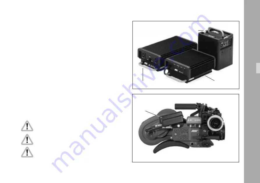
•  the battery NC 24/7 R with charger NCL 24 R 

•  the mains unit NG 12/24 R.

•  the mains unit NG 12/26 R 

➪ 

photo

.

•  the on-board battery OBB-1 with charger 

➪ 

photo

.

•  First switch on the mains unit (if used).

•  Connect the camera to the mains unit or to the battery.

•  Switch on the main switch of the camera.

Do not open the batteries! 

Charge batteries only with the proper ARRI chargers! 


Do not bypass the fuse or temperature switch! 


Do not heat NC-batteries! 

Do not short-circuit NC-batteries!

battery NC 24/7R

NCL 24 R

NC 12/26

on board battery

Power Supply

Содержание ARRIFLEX 235

Страница 1: ...ERNET SITES OR USED IN THEIR ENTIRE FORM OR IN EXCERPTS WITHOUT OUR PREVIOUS WRITTEN AGREEMENT IF YOU ARE DOWNLOADING PDF FILES FROM OUR INTERNET HOMEPAGE FOR YOUR PERSONAL USE MAKE SURE TO CHECK FOR UPDATED VERSIONS WE CANNOT TAKE ANY LIABILITY WHATSOEVER FOR DOWNLOADED FILES AS TECHNICAL DATA ARE SUBJECT TO CHANGE WITHOUT NOTICE ARRIFLEX 235 ...

Страница 2: ...ET button RS sockets LOCK button remote socket ON OFF button NORM button PS CCU button tensioning plate Integrated Video Assist IVS PL mount adjustment knob for manual image compensation lock for telecoping finder arm adjustable mirror shutter ground glass locking key for manual image compensation friction adjustment for finder arm finder arm hook for focus tape handgrip mounting point remote socket ...

Страница 3: ... System 20 Standard Camera Handle 20 Low Mode Handle 21 Low Mode Support LMS 1 22 Side Bracket SBR 1 23 4 7 Operation from the Shoulder 24 5 Power Supply 25 5 1 Battery NC 24 7 R 26 5 2 Charger NCL 24 R 26 5 3 Mains Unit NG 12 24 R 27 5 4 Mains Unit NG 12 26 R 27 5 5 Accessory Power Supply 28 24 V Accessories 28 6 Magazines 29 6 1 Loading the Shoulder Magazine 30 6 2 Removing Exposed Film 34 6 3 T...

Страница 4: ...ning Mode 4 64 Setting the Volume of the Warning Signal 64 Mode 5 65 10 Video Assist System 67 10 1 General Description of the IVS 67 Main Features 67 10 2 Setup 70 10 2 1 Installation 70 10 2 2 Cabling 72 10 3 Standard Video Controls 79 10 3 1 Switch On Off and Check Hide Menu 79 10 3 2 Mechanical Iris 80 10 3 3 Alignment of the image position X Y and Rotation and focus 81 10 3 4 White Balance WB...

Страница 5: ...trol WRC 1 143 12 Super 35 145 Converting the Lens Mount Receptacle to Normal 35 145 Converting the Bridge Plateto Super 35 146 13 Maintenance 147 Camera 148 Cleaning the Film Gate 148 Cleaning the Spacer Gate 150 Cleaning the Field Lens 151 Magazine 152 Cleaning the Throat Assembly 152 Setting Friction on the Shoulder Magazine 152 14 Appendix 155 Loose Film Loops in the Magazine 155 Fuses 155 15 ...

Страница 6: ...6 6 Contents ...

Страница 7: ...he warranty Do not repair any part of the system Repairs must only be carried out by authorized ARRI repair shops Do not remove any safety measure of the system 2 1 Safety Instructions Please always follow these instructions to help ensure against injury to yourself and damage to the system or other objects This safety information is additional to the product specific operating instructions in gene...

Страница 8: ...he cord Never insert objects of any kind into any part of the system through openings as the objects may touch dangerous voltage points or short out parts This could cause fire or electrical shock Unplug the system from the power outlet before opening any part of the system or before making any changes on the system especially the attaching or removing of cables Do not use solvents to clean Clean o...

Страница 9: ...th rotating drive gears on the lens barrel or when switching the operating direction on the UMC 1 and UMC 3 Any violation of these safety instructions or the non observance of personal care could cause serious injuries including death and damages to the system or other objects Note Notes are used to indicate further information or information from other instruction manuals photo indicates objects ...

Страница 10: ... design in refer to the latest publications of ARRI data sheets or data books etc for the most up to date specifications Not all products and or types are available in every country Please check with an ARRI sales representative for availability and additional information Neither ARRI nor its subsidiaries assume any liability for infringement of patents copyrights or other intellectual property rig...

Страница 11: ...der any other legal theory In the case one or all of the forgoing clauses are not allowed by applicable law the fullest extent permissible clauses by applicable law are validated ARRI is a registered trademark of Arnold Richter Cine Technik GmbH Co Betriebs KG Note This product and the accessories recommended by the manufacturer fulfill the specifications of the EU Guideline 89 336 EWG Safety Instru...

Страница 12: ...12 12 General Description ...

Страница 13: ...y adjustable mirror shutter on the ARRIFLEX 235 can be set to 45 60 75 90 105 120 135 144 150 172 8 and 180 The viewfinder can be rotated in two axes and can be used on both sides of the camera with full image compensation A 1 2 CCD video camera can be attached directly to the camera body The versatile grip system is connected directly to the camera body and can be used as a carrying handle or as a...

Страница 14: ...14 14 movement in locked position loop protector magazine opening cover Installation ...

Страница 15: ... or stored with the loop protector photo attached to avoid damage to the film stock and the magazine throat assembly 4 2 Tripod Heads The following tripod heads are suitable for use with the ARRIFLEX 235 ARRIHEAD ARRIHEAD 2 ARRIHEAD 2 with integrated encoders ARRI Fluid Heads Sachtler Studio 7 150 H Mitchell Head Moy Head Ronford F7 Hot Head Cam Remote Head Worall Head In applications where the cam...

Страница 16: ...y Both cylindrical pins must glide into the holes of the camera bottom 4 4 Bridge Plates BP 8 BP 9 The bridge plates facilitate balancing of the camera on the tripod and mounting of accessories The BP 8 is designed for 19 mm support rods the BP 9 for 15 mm support rods The bridge plates consist of the base plate photo the sliding upper plate photo and a pair of support rods photo In the standard v...

Страница 17: ...to the wedge plate of the tripod and lock onto the tripod head Slide the camera with the upper plate into the dovetail guide of the base plate until the spring loaded stop pin photo snaps back audibly The camera s position can then be fixed with the clamping lever Slide the support rods into the guides and clamp Equip the camera with the required accessories to determine the center of gravity Loose...

Страница 18: ...sconnected and that the eyepiece leveling rod is detached For fast removal of the camera from the tripod loosen the clamping lever photo push in the stop pin photo and then pull the camera with the upper plate photo from the base plate stop pin base plate sliding upper plate clamping lever Installation ...

Страница 19: ...front Slide the relevant support ring photo onto the lens but do not tighten Then slide the lens into the lens mount receptacle and lock Connect the support ring to the lens support and tighten the knurled screw photo as well as the clamping lever photo Complete the process by tightening the clamp screw photo on the support ring Note Mounting the support ring on the relevant lens is usually carrie...

Страница 20: ...the handle grip is positioned above the camera in the center of gravity This is useful for low handheld shots but only works with the two 235 Shoulder Magazines In the other position as seen on the photo all magazines can be accommodated The handgrip can be attached to any of the 3 8 holes by first placing the 2 pins photo into the according pin holes on the post and then fastening the handgrip scr...

Страница 21: ... to any of the 3 8 holes by first placing the 2 pins photo into the according pin holes on the handle and then fastening the extension block screw photo inside the extension block by using a long 5mm allen key Note that the viewfinder cannot be swung over to the camera right side when the Handle Extension Block is attached to the front of the Low Mode Handle Note The low mode handle is positioned in...

Страница 22: ...ounting positions on the plates one at the rear of the plate photo and one position 65mm forwards The handle can be mounted in either position facing forwards or rearwards in this way the grip balance can be adapted to best fit the magazine and lens in use The Low Mode Bracket alone offers the lowest profile and smallest plate to lens distance optimal for Steadicam applications It can be attached wi...

Страница 23: ... Bracket and both the Low Mode Bracket and Low Mode Riser offer diverse attachment points for additional accessories Side Bracket SBR 1 The 235 Side Bracket SBR 1 K2 55015 0 photo offers two adjustable 19mm support rods positioned camera right for attachment of lens motors Lightweight Follow Focus LFF 1 K0 60021 0 and other accessories with rod mounts It attaches to the 235 via the right side 3 8 ...

Страница 24: ...tach the shoulder pad to the camera body by aligning the velcro tapes photo Position the handgrip on the rosette and fasten with the fastening screw photo Plug the cable for starting and stopping the camera into the RS socket velcro tape shoulder pad RS socket handgrip RUN button shoulder pad Installation ...

Страница 25: ...nit NG 12 26 R photo the on board battery OBB 1 with charger photo First switch on the mains unit if used Connect the camera to the mains unit or to the battery Switch on the main switch of the camera Do not open the batteries Charge batteries only with the proper ARRI chargers Do not bypass the fuse or temperature switch Do not heat NC batteries Do not short circuit NC batteries battery NC 24 7R ...

Страница 26: ... Note If the battery voltage is not sufficient the bat symbol will show in the camera display 5 2 Charger NCL 24 R With this charger the battery NC 24 7 R can be charged First check whether the correct mains voltage is set on the charger Connect the charger to the mains supply Plug the charger cable into the battery socket Press the start button Indication of the LEDs LED Indication yellow discharg...

Страница 27: ... the camera and into the 24 V socket on the mains unit 5 4 Mains Unit NG 12 26 R Use of the mains unit is recommended for filming in the studio and when using electronic accessories with a high power consumption First check that the correct mains voltage is set on the mains unit Ensure that the main switch on the camera is off Set the voltage switch on the mains unit to 26 V Plug the battery cable ...

Страница 28: ...ached to the RS sockets photo At 24 V the available continuous current for both sockets together is 3 A maximum the peak load 5 A Overload Display If the current drawn at the accessory sockets exceeds the allowable maximum a self resetting safety circuit interrupts the power supply In that case turn the camera off unplug all accessories from the camera wait for one minute and turn the camera back ...

Страница 29: ...v ARRIFLEX 35 III 35 II 60 m magazine only forwards 150 m magazine forw rev Reverse operation with the ARRIFLEX 35 III 35 II 60m and the 235 shoulder magazines can lead to damage of the magazine or the camera Do not use any 300m 1000ft magazines as they could damage the camera Do not use magazines that hold more than 120m 400ft loads The camera automatically stops after a full load Note All magazi...

Страница 30: ... process considerably The ARRI Film Cutting Gauge photo simplifies cutting in the darkroom The following steps should be carried out in a darkroom or film changing bag Remove the loop protector and lay the magazine on a flat surface with its cover facing upwards To open the cover depress the safety catch flip up the locking grip and turn it counter clockwise photo Lift up the magazine cover and remove...

Страница 31: ...r until the film has been transported through the throat assembly Flip up the hinged locking clip on the feed shaft photo Place the film roll on the feed shaft ensuring that the feed shaft catch engages the slot on the plastic core Press down the hinged locking clip on the feed shaft By turning the drive gear counter clockwise transport the film further until it reaches to the loop length marking pho...

Страница 32: ...o the slit of the film core photo Wind the film on several revolutions until it is certain that the film is firmly seated on the film core Check that the film is being taken up perpendicular to the shaft photo Close the magazine cover by inserting the two latches into the slits of the magazine housing and then closing the cover The roller arm will be automatically unlocked To lock the cover turn the loc...

Страница 33: ...33 33 Note To tension the film in the magazine press in both tensioning plates photo and turn out wards tensioning plates latches Magazines ...

Страница 34: ...upwards Then turn the grip counter clock wise Lift up the cover and remove it by pulling it to the left Swing the roller arm photo away from the winding shaft until it locks in place Flip up the hinged locking clip on the take up shaft Pull the film roll upwards and off Note When pulling the film roll off the shaft grip it from underneath as far as possible to prevent the middle of the film roll from...

Страница 35: ...ed or stored with the loop protector photo attached to avoid damage to the film stock and the magazine throat assembly If the ARRIFLEX 235 is transported without a magazine it is recommended to attach the magazine opening cover photo loop protector cover for magazine opening Magazines ...

Страница 36: ...36 36 ...

Страница 37: ...positions 45 60 75 90 105 120 135 144 172 5 and 180 Setting the Mirror Shutter Angle Switch off the camera and disconnect the camera from the power supply Remove the lens or the protective cap from the lens mount receptacle Do not touch the surface of the mirror Turn the movement inching knob photo until the hole on the shutter and the hole in the camera body align photo inching knob aligning the ...

Страница 38: ...r registers properly at the set opening Pull out the shutter tool Operation of the camera when the mirror shutter is not correctly locked in position may cause incorrect exposure shutter tool Shutter Angle Measurement Holding the PHASE button depressed in standby will make the camera inch forward The display shows the measured shutter angle in the upper line The lower line displays the voltage of ...

Страница 39: ...y of the lighting and the angle of the mirror shutter must all relate to each other As the camera frame rate and the supply frequency of the lighting are normally given compensation must be carried out through the angle of the mirror shutter The following table indicates the mirror shutter angle that needs to be set Supply frequency 50 Hz 60 Hz Frame rate 25 fps 24 fps 24 fps Shutter angle 180 172...

Страница 40: ...ng the included special forceps pull the ground glass photo out of the holder by its tongue photo Check that the ground glass to be inserted as well as the ground glass frame are completely clean With the special forceps push the chosen ground glass into the holder as far as it will go The red marker point must be on the left A ball catch fixes the ground glass exactly in the right position Check t...

Страница 41: ...photo towards the OPEN position Press the spacer plate backwards by its handle photo Then remove it by pulling upwards Installing the Spacer Plate Open the movement by turning the inching knob photo until the mark aligns with the mark on the movement and then turn the movement locking lever photo towards the OPEN position Take hold of the spacer plate by its handle photo and insert it at an angle ...

Страница 42: ... the magazine s throat assembly on the lower dovetail of the camera opening With your left hand pull the film loop through the camera opening as far as possible into the movement block area photo Before locking the magazine into place ensure that the film is pulled far enough into the movement block area so that the film does not get caught between the magazine and the magazine locking mechanism Lock...

Страница 43: ...ht hand pull the film loop downwards out of the camera photo Then push it as far upwards as possible so that the film collapses on the upper film loop Insert the loop between the movement plate and the film gate Bring the film loop into position photo Position the film by one perforation hole onto the positioning pin photo in the film guide bringing the film loop to rest within the marking photo Check tha...

Страница 44: ...movement locking lever counter clockwise as far as it will go This will cause the movement block to swing forwards and to lock into position By turning the inching knob photo check that the film runs smoothly Close the camera door Note Threading the film is also described and displayed on the inside of the camera door positioning pin loop marking movement locking lever inching knob Camera Body ...

Страница 45: ...ssembly Ensure that the loop does not get twisted behind the movement block as otherwise the film could be damaged when removing the magazine Swing the movement block forwards again and lock Hold the magazine firmly with one hand and pull the magazine locking lever back with the other When pulling away the magazine ensure that the film does not get damaged Pull the magazine off upwards Replace the co...

Страница 46: ...46 46 ...

Страница 47: ...se as far as it will go and then pulling out the protective cap Never put your fingers into the lens mount receptacle Push the lens into the lens mount receptacle without catching it at the edges One of the four slots on the lens mount must fit over the index pin photo Press the lens flat onto the lens mount receptacle and pull the bayonet ring clockwise to tighten Note The camera is delivered in Sup...

Страница 48: ...he Eyepiece Removing the Eyepiece Hold the eyepiece with one hand and with the other turn the knurled ring eyepiece photo towards the OPEN position as far as it will go Remove the eyepiece photo Attaching the Eyepiece Ensure that the knurled ring is turned to the OPEN position Position the eyepiece on the viewfinder Turn the knurled ring eyepiece photo towards the LOCK position Check that the eyepi...

Страница 49: ...y friction To set friction turn the knurled knob photo right left until the desired friction has been reached Swivelling the Viewfinder Arm The viewfinder arm can be swivelled approx 270 left to right On the left side of the camera the viewfinder arm locks into the horizontal position The viewfinder arm friction can be altered if necessary by turning the allen screw photo To adjust the viewfinder arm r...

Страница 50: ... knurled ring Image Compensation The viewfinder system is fitted with an automatic image compensation mechanism To enable setting a different image position in certain situations the viewfinder system is additionally equipped with a manual image adjustment mechanism Manually Adjusting Image Compensation Depress the locking key photo and hold depressed Turn the adjustment knob photo until the viewfinde...

Страница 51: ...e adjusted to the opposite locking position Inverting the Image Depress the locking key photo and keep depressed Turn the adjustment knob photo Release the locking key photo Keep turning the adjustment knob photo until this locks in position Removing the Viewfinder System Before removing the viewfinder system the viewfinder arm should be brought back to its normal position Loosen the three fastening ...

Страница 52: ...52 52 Optics ...

Страница 53: ...ower cable is unplugged and then plugged in again the camera will be on or off depending on ist state before the camera cable was unplugged 9 2 Running and Stopping the Camera A RUN button is located on the left and on the right side of the camera photo Running the Camera If the operation control indicator glows red while in standby the camera is not ready and will not run see Overview of Display ...

Страница 54: ...press the RUN button photo briefly While the camera is running down the operation control indicator glows red The mirror shutter automatically stops in a position that enables unrestricted viewing through the viewfinder On reaching this position the operation control indicator flashes green before going out ON OFF button RUN button RUN button operational control indicator PHASE button black bar to in...

Страница 55: ...ional parameters on the ARRIFLEX 235 are displayed on the camera display photo in various modes The desired mode is selected via the MODE button In each mode the corresponding operational parameters can be set using the SEL and SET buttons photo Note The Mode numbers are shown in the display between the upper and the lower line Mode 1 is also indicated photo in the display by a black horizontal ba...

Страница 56: ...ration of the 1st display line frame rate fps while running external control connected Mode 2 programmed frame rate PS programmed frame rate fps programmed frame rate ESU external control connected forwards reverse Mode 3 total exposed film counter m ft or power supply voltage V configuration of the film counter take counter m ft unit of measurement m ft Mode 4 volume of the acoustic warning signal b...

Страница 57: ...set NORM speed PS CCU glows camera will run the set PS speed or the speed set by an accessory LOCK glows display is locked m ft glows indicates the unit in which the film consumption is counted glows display shows the current shutter angle R glows Reverse operation is switched on Display Movement Open The display shows if the movement film transport thus trAnS has not been locked correctly into oper...

Страница 58: ...values are shown in Modes 1 and 3 Two different counting values are shown respectively the total amount of exposed film or the take length amount of film used in an individual take A t in the first digit of the upper display line indicates the display of take length RUN button operational control indicator PHASE button black bar to indicate Mode 1 Camera Operation ...

Страница 59: ...hich shows the total amount of exposed film MODE button The total exposed film counter can be set to zero by depressing the SET button for at least 1 5 seconds while in standby The take length counter is automatically reset each time the camera is started Changing the Unit of Measurement Meters Feet Mode 3 Change from Mode 1 to Mode 3 by depressing the MODE button twice Depress the SEL button once t...

Страница 60: ...ons photo on the right of the camera The NORM setting corresponds to the standard frame rate the PS CCU position to the freely programmed frame rate Selecting a Standard Frame Rate Mode 1 Standby Operation The camera must be in Mode 1 and the camera must be set to NORM Depress the SEL button repeatedly until the desired frame rate is selected Within 3 seconds confirm this choice by depressing the S...

Страница 61: ...ps forward and 25 fps reverse Note The programmed frame rate is stored in a non volatile memory Switching Between Forward and Reverse Operation Mode 2 Standby Operation Change from Mode 1 to Mode 2 by depressing the MODE button once Depress the SEL button Cd Camera direction blinks Hold the SET button depressed for more than three seconds The display shows an R for reverse operation at the bottom ...

Страница 62: ... the camera Depress the MODE button once to change to Mode 2 With the buttons SEL slower and SET faster change the frame rate PS CCU button NORM button RUN button operational control indicator PHASE button Shifting Phase To film quartz synchronized monitors hold the PHASE button photo depressed after the camera has run up until the horizontal bar is no longer visible in the viewfinder The frame rate...

Страница 63: ...wn in the lower line of the display Setting the brightness of the button illumination Change from Mode 1 to Mode 4 by depressing the MODE button three times Depress the SEL button three times to activate the display for setting the button illumination Select the desired brightness using the SET button 0 off 3 maximum brightness Camera Operation ...

Страница 64: ... SET button to select one of the four settings Depressing the MODE button confirms the selection Display Warning tone on start Warning tone on stop LS _ _ off off LS _ on off LS _ off on LS on on Setting the Volume of the Warning Signal Change from Mode 1 to Mode 4 by depressing the MODE button three times Depress the SEL button two times to activate the display for setting the warning signal volum...

Страница 65: ...n up speed blinks Select the desired run up speed by pressing the SEL button setting ramping speed LO 25f s2 HI 40f s2 Displaying software versions Press SET for three seconds in the rampspeed menu the first line will display Sxx xx for the camera software version The second line will display Fxx xx for the FPGA software version Press SEL the first line will display bxx xx for the bootloader softwar...

Страница 66: ...activate on screen program mode or store position of inserted window or store user text increase gain or cursor up or move inserted window up or increase blue increase format numbers or go to submenu or increase values or increase red decrease format numbers or go into submenu or decrease values or decrease red decrease gain or cursor down or move inserted window down or decrease blue Y adjustment...

Страница 67: ...0 and one of the most sensitive CCD Chips available on the market provide an excellent color video image in editing quality even when the light is set for high speed film stock to be pushed during processing High resolution The design of the new IVS optics was based on the ARRIFLEX 235 viewfinder data and resulted in an image quality which cannot be attained by add on solutions Flicker free An integ...

Страница 68: ...lectronically in 4 different steps to emphasize the important image area Camera status display Camera status information e g camera speed and film counter data are passed on a bus interface from the camera to the video assist and can be displayed in a camera status line on the monitor System display Camera system information is available in the video assist Thus it is possible to see camera warning...

Страница 69: ...This clearly shows the difference between the images e g during stop effect shots Automatic and manual gain control The gain is controlled automatically to its best value but can also be set manually Mini monitor connector The IVS offers a connector for a 12 V LCD mini monitor with an even increased output power up to 1 5 A Note The IVS package already includes a lens for Super 35 a 1 5 mm allen k...

Страница 70: ...cover off the camera To take the handle off open the two screws on the base of the handle photo with a 3 mm allen key and remove the handle To take the transport cover off open the two screws photo with a 3 mm allen key and remove the transport cover screws for handle handle screws for transport cover Video Assist System ...

Страница 71: ...ort cover to the rear Pull off the plastic cover over the contacts Attach the video assist onto the ARRIFLEX 235 by moving it in the marked direction The wedge on the IVS should mate with the matching dovetail on the camera body photo screws for cover on the IVS cover on the IVS plastic cover for contacts dovetail Video Assist System ...

Страница 72: ...should be used and it is unknown weather the BNC connectors on the IVS are switched to composite or to Y C please connect the composite signal to the É Y first and check the settings BNC OUT VBS or Y C in the menu video text adjust Please see next chapter Composite Video Outputs The IVS has two BNC sockets which can be switched to output two independent composite signals or one Y C signal Additiona...

Страница 73: ... connector and video with data on the other In the normal video output marked with the È C symbol photo almost no electronic information is inserted Only a rolling bar at the button left corner of the video image indicates a running film camera In the video with data output marked with the É Y symbol photo additional data such as format marks or camera status information can be inserted The outputs...

Страница 74: ...ogram mode to switch between composite and Y C Enter the main menu by pressing the Enter Insert key Ñ for more than 3 seconds Go to sub menu VIDEO TEXT ADJUST The menu line BNC OUT can be switched between VBS and Y C See chapter 10 4 Inserter Facilities for information on the on screen program mode MENU VIDEO TEXT ADJUST FLICKERFREE ON LINE INTERP ON BNC OUT Y C Y C DATA MINI MON DATA ON TXT WHITE...

Страница 75: ... signal The line displays Y C DATA ON or OFF See chapter 10 4 Inserter Facilities for information on the on screen program mode In the normal video output almost no electronic information is inserted Only a rolling bar at the lower left corner of the video image indicates a running film camera In the video with data output additional data such as format marks or camera status information can be ins...

Страница 76: ... between composite and Y C Enter the main menu by pressing the Enter Insert key Ñ for more than 3 seconds Go to sub menu VIDEO TEXT ADJUST The menu line BNC OUT can be switched between VBS and Y C See chapter 10 4 Inserter Facilities for information on the on screen program mode There are normal video and video with data signals available from the same connector MENU VIDEO TEXT ADJUST FLICKERFREE ...

Страница 77: ...deo with data on the Y C signal The line displays Y C DATA ON or OFF See chapter 10 4 Inserter Facilities for information on the on screen program mode In the normal video output almost no electronic information is inserted Only a rolling bar at the lower left corner of the video image indicates a running film camera In the video with data output additional data such as format marks or camera statu...

Страница 78: ...y pressing the Enter Insert key Ñ for more than 3 seconds Go to sub menu VIDEO TEXT ADJUST The menu line MINI MON DATA can be switched OFF and ON See chapter 10 4 Inserter Facilities for information on the on screen program mode MENU VIDEO TEXT ADJUST FLICKERFREE ON LINE INTERP ON BNC OUT Y C Y C DATA ON MINI MON DATA ON TXT WHITE LEV 2 TXT INVERS ON TXT FINE POS 2 EXIT mini monitor connector Pin ...

Страница 79: ...The IVS can be switched on and off independently from the film camera as long as the film camera has power Power off at the film camera will also shut the IVS down photo The OFF position switches the IVS off without affecting the film camera ON activates the IVS Check Menu If the on screen program mode is off during normal operation the Menu M position shows an overview of the IVS settings photo switc...

Страница 80: ...elatively small portion of the light that passes through the film camera s lens reaches the CCD Chip of the video assist as the light is shared between the view finder the CCD Chip and the film Therefore the IVS lenses are designed for normal usage with a totally open iris to have maximum light on the CCD Chip Variations in lighting are compensated by the IVS gain control automatically or manually Un...

Страница 81: ...era The video image on the monitor may appear not centered rotated or out of focus All settings can be made by using a 1 5 mm allen key which is delivered with the IVS Do not use force Image position adjustments in x and y direction can be made with the marked x and y screws photo The screw marked with Ò moves the video image on the monitor horizontally The screw marked with Ó vertically Ó alignme...

Страница 82: ...r coded Ê Ë Í and Ì keys The next click on the WB key Ï or waiting longer than 5 seconds without pressing any key will cause the MAN LED to be constantly on Another click on the WB key Ï will lead back to AWB An illuminated LED shows the selected mode If automatic White Balance AWB is selected the IVS will automatically set White Balance For this no manual steps are necessary photo If indoor IND i...

Страница 83: ... and Ë to the line WHITE BALANCE Pressing the key Í will switch from Automatic White Balance AWB Indoor IND and Outdoor OTD to Manual MAN and back Automatic White Balance The key Ì will give the opposite direction If white balance is on manual the display will change Lines left of RED and BLUE will appear indicating that the red and green saturation of the video image can now be changed MENU WB GA...

Страница 84: ...ng the key Í will increase the red in the video image the key Ì will decrease it The range for this is from 0 lowest to 63 highest If the key Í or Ì is pressed shortly the value is changes by one step if the keys are pressed longer the value will continue to change The LED in the keyboard will follow the changes which are made in this menu and vice versa if this setting is changed via the keyboard...

Страница 85: ...ing the key Í will increase the blue in the video image the key Ì will decrease it The range for this is from 0 lowest to 63 highest If the key Í or Ì is pressed shortly the value is changes by one step if the keys are pressed longer the value will continue to change The LED in the keyboard will follow the changes which are made in this menu and vice versa if this setting is changed via the keyboa...

Страница 86: ... different ways It is possible to control it using the keyboard on the IVS or using the on screen control menu Using the Keyboard Check all settings on the connected monitor By pressing the WB key Ï the setting alters between manual and automatic control An illuminated LED shows the setting manual gain control MGC photo If manual gain control is selected LED is on the brightness of the video image...

Страница 87: ... to sub menu WB GAIN Move the cursor with the keys Ê and Ë to the line MANUAL GAIN Pressing the key Í or Ì will switch manual gain control off and on If manual gain control is on the display will change A line symbol will appear before VALUE indicating that the gain can be changes manually The LED in the keyboard will follow the changes which are made in this menu and vice versa if this setting is...

Страница 88: ...e for this is from 0 lowest gain to 63 highest gain If the key Í or Ì is pressed shortly the value is changes by one step if the keys are pressed longer the value will continue to change The LED in the keyboard will follow the changes which are made in this menu and vice versa if this setting is changed via the keyboard the on screen menu will follow MENU WB GAIN WHITE BALANCE MAN RED 30 BLUE 39 M...

Страница 89: ...ate this so called flicker video images are stored at the speed of the film camera into the video frame storage and recalled in the speed of the video system This storage might cause a slight delay which is not desirable in some crucial time conditions e g motion control or shooting of a pop video Therefore it is possible to switch the flicker free system off This will eliminate the delay However flic...

Страница 90: ...for more than 3 seconds Go to sub menu VIDEO TEXT ADJUST Move the cursor with the keys Ê and Ë to the line FLICKERFREE Pressing the key Í or Ì will switch flicker free mode off and on Note The lowest camera speed for flicker free display is 5 fps in automatic gain control mode and 1 fps in manual gain control mode MENU VIDEO TEXT ADJUST FLICKERFREE ON LINE INTERP ON BNC OUT VBS Y C DATA MINI MON DAT...

Страница 91: ... be done via the on screen display as described in chapter 10 4 6 Format Marking Menu However it is possible to select which format markings are displayed via the keyboard The format marking selection is only available when the White Balance manual mode is not active when the WB MAN LED is not flashing If white balance manual mode is active please wait for more than 5 seconds without pressing any k...

Страница 92: ... the on screen menu Enter the main menu by pressing the Enter Insert key Ñ for more than 3 seconds Go to sub menu FORMAT MARKING Move the cursor with the keys Ê and Ë to the line FORMAT Pressing the key Í will switch from OFF 1 2 to 1 2 The key Ì will switch in opposite order MENU FORMAT MARKING FORMAT OFF POSITION 1 Ö POSITION 1 Ü POSITION 2 Ö POSITION 2 Ü WHITE LEVEL OUTSIDE EXIT Video Assist Sy...

Страница 93: ...y available in the on screen program mode it is possible to store an image any time using the Enter Insert key Ñ Using the Keyboard Pressing the Enter Insert key Ñ shortly less than 1 5 seconds will store an image in the frame store Every time when the Enter Insert key Ñ is shortly pressed a new image is stored To view the stored image or to compare it against a live image please enter the on scre...

Страница 94: ...menu COMPARE STORE Move the cursor with the keys Ê and Ë to the line STORE IMAGE Pressing the key Í or Ì will store the image The word DONE will appear for a few seconds to show that an image was stored The stored image is memorized until a new image is stored the image is cleared or until the IVS power was shot down MENU COMPARE STORE VIEW MODE LIVE STORE IMAGE CLEAR IMAGE EXIT Video Assist Syste...

Страница 95: ...n if the IVS or the camera is switched off or disconnected from the power supply After restarting the IVS the settings are unchanged except for the image stored mode which will always come up in live mode 10 4 1 Setting the On Screen Displays During programming the inserted data are not fully updated e g Frame Counter Information To get information updated leave the on screen display menu by press...

Страница 96: ...arked with a dash symbol They can be reached with the cursor within a menu using the keys Ê and Ë Lines may not be active because the currently selected mode does not use this feature E g when gain is not in manual control mode the line value is not active because value cannot be changed in the automatic control mode In this case no dash symbol is displayed and the line cannot be reached with the ...

Страница 97: ...mming is activated Note Pressing the Enter Insert key Ñ for more than three seconds will cause the system to exit the on screen programming mode completely regardless of which menu is activated with the exception of the positioning mode The keys Ê or Ë move the cursor up or down Pressing the key Í or Ì will lead into a sub menu MAIN MENU LOAD STORE WB GAIN VIDEO TEXT ADJ FORMAT MARKING COMPARE STO...

Страница 98: ...t electronically will be stored and recalled All video adjustments such as manual gain control white balance flicker free outputs with or without data and line interpolation as well as all inserter setups e g user text insertion off or on frame lines and so on are stored and recalled The adjustment of the white level of the inserted data an inverse display and a fine adjustment of the vertical posit...

Страница 99: ...d the new settings Store Settings The set of settings that are currently active can be stored as one out of six settings Move the cursor with the keys Ê and Ë to the line STORE SET Pressing the key Í will switch from 1 to 2 all the way up to 6 and back to 1 the key Ì will switch in the opposite direction When the demanded number was reached press the Enter Insert key Ñ to store this setting under ...

Страница 100: ...firm that procedure as all settings will be cleared This window will appear with the cursor in the line NO Pressing the key Í or Ì will cancel this procedure To clear everything move the cursor with the keys Ê and Ë to the line YES Pressing the key Í or Ì sets all settings to default If the cursor is in position EXIT and the key Í or Ì is pressed the IVS will return to the Load Store menu without s...

Страница 101: ...USER TEXT LINE OFF Background User Text line boxed Size Small White Level Text 2 Inverse OFF Vert Pos 5 MENU LOAD STORE LOAD SET 4 STORE SET 4 CONFIRM BY ENTER SET ALL SETTINGS TO DEFAULT EXIT Exit Use exit to return to the main menu Move the cursor with the keys Ê and Ë to the line EXIT and press the key Í or Ì Note Pressing the Enter Insert key Ñ for more than three seconds will cause the system...

Страница 102: ... In parallel to the control via keyboard the white balance can also be programmed via the on screen menu It toggles from Indoor Outdoor and Automatic to Manual Move the cursor with the keys Ê and Ë to the line WHITE BALANCE Pressing the key Í will switch from Automatic White Balance AWB Indoor IND and Outdoor OTD to Manual MAN and back Automatic White Balance The key Ì will give the opposite direc...

Страница 103: ...e cursor with the keys Ê and Ë to the line RED Pressing the key Í will increase the red in the video image the key Ì will decrease it The range for this is from 0 lowest to 63 highest If the key Í or Ì is pressed shortly the value is changes by one step if the keys are pressed longer the value will continue to change The LED in the keyboard will follow the changes which are made in this menu and v...

Страница 104: ...sing the key Í will increase the blue in the video image the key Ì will decrease it The range for this is from 0 lowest to 63 highest If the key Í or Ì is pressed shortly the value is changes by one step if the keys are pressed longer the value will continue to change The LED in the keyboard will follow the changes which are made in this menu and vice versa if this setting is changed via the keybo...

Страница 105: ...he line MANUAL GAIN Pressing the key Í or Ì will switch manual gain control off and on If manual gain control is on the display will change A line symbol will appear before VALUE indicating that the gain can be changes manually The LED in the keyboard will follow the changes which are made in this menu and vice versa if this setting is changed via the keyboard the on screen menu will follow MENU W...

Страница 106: ... the key Ì will decrease it The range for this is from 0 lowest gain to 63 highest gain If the key Í or Ì is pressed shortly the value is changes by one step if the keys are pressed longer the value will continue to change The LED in the keyboard will follow the changes which are made in this menu and vice versa if this setting is changed via the keyboard the on screen menu will follow MENU WB GAI...

Страница 107: ... key Í or Ì Note Pressing the Enter Insert key Ñ for more than three seconds will cause the system to exit the on screen programming mode completely regardless of which menu is activated with the exception of the positioning mode MENU WB GAIN WHITE BALANCE IND RED BLUE MANUAL GAIN ON VALUE 40 EXIT Video Assist System ...

Страница 108: ...ns at 24 fps and the video assist at 25 fps for PAL or 30 fps for NTSC This would normally cause different brightness of the video image To eliminate this so called flicker video images are stored at the speed of the film camera into the video frame storage and recalled in the speed of the video system This storage might cause a slight delay which is not desirable in some crucial time conditions e g...

Страница 109: ... true video field and the next one will be the repetition of the previous one So the repeated video field does not have new information To improve this situation the video assist can be electronically enhanced with a so called line interpolation Move the cursor with the keys Ê and Ë to the line LINE INTERP Pressing the key Í or Ì will switch the line interpolation on and off Note This setting affect...

Страница 110: ...dicating that the Y C output can now be switched between normal video and video with data Y C signal with or without data There are normal video and video with data signals available from the same pair of connectors Therefore it is necessary to switch between the two types of video Move the cursor with the keys Ê and Ë to the line Y C DATA Pressing the key Í or Ì will switch between normal video a...

Страница 111: ... data in the mini monitor ON and OFF White Level This line is used to change the brightness of all man readable windows but the frame lines Value 0 means dark gray value 3 corresponds to bright white characters Move the cursor with the keys Ê and Ë to the line TXT WHITE LEV By pressing the key Í the values for the brightness of the characters will increment beginning from 0 to 3 and after that bac...

Страница 112: ...line fine adjust The single steps are smaller than the steps in the normal position mode This will place all windows as far outside the actual image area as possible Format markings are not moved Move the cursor with the keys Ê and Ë to the line FINE POS By pressing the key Í the value will increment starting from 0 to 9 after that it will go back to 0 Higher values will cause the windows to be at ...

Страница 113: ...nsert key Ñ for more than three seconds will cause the system to exit the on screen programming mode completely regardless of which menu is activated with the exception of the positioning mode MENU VIDEO TEXT ADJUST FLICKERFREE ON LINE INTERP ON BNC OUT VBS Y C DATA ON MINI MON DATA ON TXT WHITE LEV 2 TXT INVERS ON TXT FINE POS 5 EXIT Video Assist System ...

Страница 114: ...up exactly with the ground glass markings The brightness is adjustable in four steps and the area outside of one format marking can be electronically darkened Changing them immediately activates all settings Check all settings on the connected monitor Enter the Format Marking submenu from the main menu MENU FORMAT MARKING FORMAT 1 POSITION 1 Ö POSITION 1 Ü POSITION 2 Ö POSITION 2 Ü WHITE LEVEL 2 O...

Страница 115: ...mat 1 is on only POSITION 1 can be reached with the cursor Only if format 1 2 is selected all POSITION lines can be used It is possible to have no format marking OFF format marking number one 1 format marking number two 2 or both format markings at the same time 1 2 on display Move the cursor with the keys Ê and Ë to the line FORMAT Pressing the key Í will switch from OFF to 1 to 2 to 1 2 and back...

Страница 116: ... the line POSITION 1 Ö or POSITION 2 Ö depending on whether format 1 or format 2 should get adjusted The symbol Ö indicates that the top line and the left line can be moved To move the top line up and down use the keys Ê and Ë to move the left line left and right use the keys Í and Ì Move the cursor with the keys Ê and Ë to the line POSITION 1 Ü or POSITION 2 Ü depending on whether format 1 or for...

Страница 117: ... No darkening function is available if there is no format marking or if two format markings are switched on The brightness of the area outside of one format marking can be reduced electronically to emphasize the important image area Move the cursor with the keys Ê and Ë to the line OUTSIDE Pressing the key Í will switch from no shading VID light shading LIGHT dark shading DARK to BLACK and back to...

Страница 118: ...ing the Enter Insert key Ñ for more than three seconds will cause the system to exit the on screen programming mode completely regardless of which menu is activated with the exception of the positioning mode MENU FORMAT MARKING FORMAT 1 POSITION 1 Ö POSITION 1 Ü POSITION 2 Ö POSITION 2 Ü WHITE LEVEL 2 OUTSIDE LIGHT EXIT Video Assist System ...

Страница 119: ...Ê and Ë to the line VIEW MODE Pressing the key Í will switch from LIVE to STORE to COMP and back to LIVE The key Ì will give the opposite direction If LIVE is selected the actual image will be displayed If STORE is selected an image which was stored before will be displayed and if COMP is selected a live image and a stored image will alternate to show the difference of both images MENU COMPARE STO...

Страница 120: ...d Compare Move the cursor with the keys Ê and Ë to the line STORE IMAGE Pressing the key Í or Ì will store the image The word DONE will appear for a few seconds to show that an image was stored The stored image is memorized until a new image is stored the image is cleared or until the IVS power was shot down Clear image To clear an image move the cursor with the keys Ê and Ë to the line CLEAR IMAG...

Страница 121: ...the key Í or Ì Note Pressing the Enter Insert key Ñ for more than three seconds will cause the system to exit the on screen programming mode completely regardless of which menu is activated with the exception of the positioning mode MENU COMPARE STORE VIEW MODE LIVE STORE IMAGE CLEAR IMAGE EXIT Video Assist System ...

Страница 122: ... data in the film camera MENU SYSTEM STATUS SYSTEM LINE ON STATUS LINE ON POSITION BACKGROUND BOXED FILM COUNTER FTGE EXIT MOVEMENT OPEN 25 7V NRDY FWD 0 000 24 000 180 0 F OM 25 7V NRDY FWD 0 000 24 000 180 0 F OM fi l m c a m e r a v o l t a g e i n s t a n d b y S T B Y r u n R U N o r n o t r e a d y N R D Y s e l e c t e d fi l m c a m e r a d i r e c t i o n f o r w a r d F W D o r r e v e r s ...

Страница 123: ...ackage If both lines are on the upper line will always be status the lower line system Positioning always affects both lines Like all man readable information the data is inserted as a window on the monitor image The window can be switched on and off independently Background and position can be altered without affecting the settings of other windows MENU SYSTEM STATUS SYSTEM LINE ON STATUS LINE ON...

Страница 124: ...r Ì switch the insertion on and off A line similar to the depicted line will appear MOVEMENT OPEN Position and Background is only available if one of the two lines in on Film Counter only if Status Line is on To clear this message eliminate the cause of the problem In this example close the movement block MENU SYSTEM STATUS SYSTEM LINE OFF STATUS LINE OFF POSITION BACKGROUND FILM COUNTER EXIT Vide...

Страница 125: ...to the line STATUS LINE The keys Í or Ì switch the insertion on and off A line similar to the depicted line will appear MENU SYSTEM STATUS SYSTEM LINE OFF STATUS LINE OFF POSITION BACKGROUND FILM COUNTER EXIT 25 7V STBY FWD 0 000 24 000 180 0 F 0M Position and Background is only available if one of the two lines in on Film Counter only if Status Line is on Video Assist System ...

Страница 126: ...by pressing the Enter Insert key Ñ Background The background of the window can be set electronically to black in normal display mode or to white in inverse mode BOXED to improve the readability If this is not activated the area around the text is the normal video image VIDEO Move the cursor with the keys Ê and Ë to the line BACKGROUND The key Í or Ì switches between BOXED and VIDEO MENU SYSTEM STA...

Страница 127: ...ing of the camera If meter are selected there the data in the IVS are displayed in meter Exit Use exit to return to the main menu Move the cursor with the keys Ê and Ë to the line EXIT and press the key Í or Ì Note Pressing the Enter Insert key Ñ for more than three seconds will cause the system to exit the on screen programming mode completely regardless of which menu is activated with the except...

Страница 128: ...his might be for example the production name Like all man readable information the data is inserted as a window on the monitor image The window can be switched on and off independently Background position and character format can be altered without affecting the settings of other windows This additional line shows the text information similar to this PROD NAME UNIT A TAKE 35 SCENE 11 III MENU USER...

Страница 129: ...F independently of other inserted data Move the cursor with the keys Ê and Ë to the line USER TEXT LINE The keys Í or Ì switch the insertion on and off The default text is all characters dotted Edit Text The text can be edited on the IVS without the need for additional devices Move the cursor with the keys Ê and Ë to the line EDIT TEXT Activate the edit menu with the keys Í or Ì This will lead int...

Страница 130: ...n To leave the text edit mode press the Enter Insert key Ñ This will lead back to the user text menu Clear Text The user text line can be cleared on the IVS without an external device When the text is cleared the default line a dotted line will appear A cleared line cannot be recalled any more Move the cursor with the keys Ê and Ë to the line CLEAR TEXT Pressing the keys Í or Ì will clear the line...

Страница 131: ...tion has been set confirm by pressing the Enter Insert key Ñ Size The size of the window can be changed independently from other inserts Move the cursor with the keys Ê and Ë to the line SIZE The key Í will switch from SMALL WIDE HIGH to BIG and back to SAMLL The Ì key will switch in opposite direction MENU USER TEXT USER TEXT LINE ON EDIT TEXT CLEAR TEXT POSITION SIZE SMALL BACKGROUND BOXED EXIT M...

Страница 132: ...XED to improve the readability If this is not activated the area around the text is the normal video image VIDEO Move the cursor with the keys Ê and Ë to the line BACKGROUND The key Í or Ì switches between BOXED and VIDEO MENU USER TEXT USER TEXT LINE ON EDIT TEXT CLEAR TEXT POSITION SIZE SMALL BACKGROUND BOXED EXIT Video Assist System ...

Страница 133: ... the main menu Move the cursor with the keys Ê and Ë to the line EXIT and press the key Í or Ì Note Pressing the Enter Insert key Ñ for more than three seconds will cause the system to exit the on screen programming mode completely regardless of which menu is activated with the exception of the positioning mode Video Assist System ...

Страница 134: ...134 134 Accessories ...

Страница 135: ...nting Points On the camera body and on the electronic cover there are accessory mounting points Various accessories can be mounted to them by using 3 8 screws Check that the screws are not reaching more than 9mm into the camera body from the contact surface photo otherwise the camera can be damaged accessory mounting points ...

Страница 136: ...in function to those on the standard viewfinder The anamorphic viewfinder can also be used together with the 235 finder extender Adjusting the UV 1 Unlike the standard viewfinder the anamorphic viewfinder will only provide an undistorted image in horizontal locked position The locking stops of the UV 1 can be adjusted to an exactly horizontal position Loosen do not remove the two allen screws photo in ...

Страница 137: ...d with the mechanical aperture Heated Eyecup HE 4 The heated eyecup prevents the eyepiece photo from fogging in low temperatures e g when filming outdoors in winter Pull the normal eyecup off the eyepiece then place the heated eyecup on the eyepiece Plug the heated eyecup with cable KC 42S to the RS socket Set the heating level with the toggle switch photo LO low heat output HI higher heat output I...

Страница 138: ...138 138 Remote Run Switch RS 4 Attach the remote run switch with the spring clamp photo e g to the pan handle Plug the RS 4 plug into the RS socket Accessories ...

Страница 139: ...he upper line The ESU 1 can be used for frame rates from 3 to 60 fps The frame rate is indicated on the camera display in Mode 2 A phase shifter and a pilottone generator have also been integrated into the external synchronization unit The synchronization is retained even when the camera is switched off See TECHN INFORMATION External Synchronization Unit ESU 1 To connect the ESU cable to the camer...

Страница 140: ...a certain period of time These programs can be recalled repeatedly as necessary The RCU 1 automatically calculates the actual screen time for the programmed speed ramps Running values can be regulated with the large handwheel The free programming of end stops to individually defined minimum and maximum values is particularly comfortable The illuminated LCD display quickly precisely and comprehensiv...

Страница 141: ...o on the camera For further information see the RCU 1 instruction manual Note The RCU 1 will always operate in the HI ramping speed Operation in LO is not possible CCU and RU are not supported and could cause malfunction when connected Remote socket Accessories ...

Страница 142: ...h SEL button MODE button OPEN PHASE button handwheel ON button RELEASE button radio channel RF LED CAL LED CAL button READY LED BAT LED RUN LED RUN button READY LED COMPENSATION rotary switch RUN LED SET button RAMP button WRC 1 with WMU 3 WRC 1 with WMU 1 Accessories ...

Страница 143: ...dwheel permits sensitive adjustment of operational values and easy pro gramming of end stops for user defined minimum and maximum values The illuminated LCD provides quick precise and compre hensive information about all the settings the status of the camera and the WRC 1 including all warnings The WRC 1 is the perfect addition to the ARRI Wireless Lens Control System Connected to the Wireless Main...

Страница 144: ...144 144 Super 35 ...

Страница 145: ...bridge plate must be altered for the format This ensures that the lenses and accessories are exactly aligned to the optical center of Normal 35 Converting the Lens Mount Receptacle to Normal 35 For shooting in Normal 35 the lens mount receptacle must be turned 180 Remove the six cylindrical screws photo Unscrew both locking grips photo Turn the lens mount receptacle so that the number 1 is positio...

Страница 146: ...dex arrows on the sliding upper plate The bridge plate can be converted to Super 35 as follows Remove the two screws photo Turn the compensation bar 180 and screw tightly in this position Note The viewfinder system is so designed that no alteration is necessary for shooting in Super 35 screws index arrows Super 35 ...

Страница 147: ...cloths and swabs Also suitable are special cleaning tissues and small sponges as used in cleaning com puters and video equipment When cleaning the film movement do not exert too much pressure Use only the prescribed special tools Use only screwdrivers of the correct size From time to time at the latest however after the occurrence of a film jam it is recommended to clean the entire interior of the c...

Страница 148: ...s may dirty or damage the mirror shutter To remove the film gate Switch off the camera s main switch and disconnect the camera from the power supply before removing the film gate Turn the inching knob photo on the movement until its marking matches that on the movement block Turn the movement locking lever photo towards the OPEN position to swing the movement block away from the film gate Pull the fil...

Страница 149: ...ty Inserting the film gate Warning It is absolutely essential to ensure that the connecting surfaces are free of dust and debris e g film chips in order to guarantee the accuracy of the film channel Check that the film gate and the film gate guide rails are completely free of dust and dirt Take hold of the film gate by the film gate handle and push it back into place Check that the film gate is pushed all...

Страница 150: ...Press the spacer gate backwards by its handle photo Then remove by pulling upwards Remove the layer of emulsion from the spacer gate photo with a plastic rod e g an ARRI film gate cleaner Under no circumstances use hard or metal objects When cleaning pay particular attention to the spacer gate if film stock with a strong tendency to build up emulsion e g b w stock is being used Take hold of the spac...

Страница 151: ...ial forceps first lift the field lens photo upwards by its tongue photo then pull it out of its holder Clean the field lens with a dry lint free cloth Make sure that the frame is completely clean Using the special forceps push the field lens as far as it will go into the holder A ball catch fixes the field lens in the correct position Check if the ground glass to be used and the ground glass frame are c...

Страница 152: ...ver back in place Replace the holder plate for the loop protector and re tighten the throat assembly cover with the three screws Setting Friction on the Shoulder Magazine Swing the roller arm photo away from the winding shaft until it locks in place Unscrew the three screws on the transparent tensioning plate photo Remove the plate Place a film core on the take up side Place the core adapter photo ...

Страница 153: ... supply Place the special key photo in the holes of the friction adjustment and turn in steps The adjustment must lock in at each step When setting friction the corresponding winding shaft must be held firmly Turn clockwise to increase friction counter clockwise to decrease friction Connect the camera to the power supply and switch on Run the camera at 24 fps Check the tension Note Repeat this proc...

Страница 154: ...154 154 Maintenance ...

Страница 155: ...ra display shows the warning for asynchronous running asy Loose Film Loops in the Magazine If the camera shuts off automatically while running loose film loops may be formed in the magazine Before the camera is started again the film in the magazine must be tensioned manually Fuses The ARRIFLEX 235 is equipped with self resetting automatic fuses It is therefore not necessary to replace blown fuses A...

Страница 156: ...Hot motor excess temperature maximum motor temperature has been exceeded wait until motor has cooled down Error CntL Controller Error internal controller limits have been exceeded check if camera is jammed Updt software update in progress camera software and firmware is updated Async camera speed is not the choosen speed inching camera is inching low battery camera supply voltage too low change bat...

Страница 157: ...gate and magazine throat on the film gate or or film running surfaces in the magazine throat if defective replace Scratches on the glossy side of the negative In the image area Dirty or damaged film track Clean film track movement and spacer gate or or spacer gate if defective replace Outside the image area Dirty or damaged longitidinal bars Carefully clean longitudinal bars and on the film track magaz...

Страница 158: ... film gate area Clean film gate area film edge is not straight use different film stock Pressure exposures Mechanical stress Pressure exposures do not effect arround perforation holes on the perforation holes the image steadiness Image Problems Blurred image Flange focal distance is incorrectly set When cleaning or exchanging the film gate lens is incorrectly set ensure that the surfaces are absolutely...

Страница 159: ...e of the battery Check the battery charge following the directions the selected frame rate is insufficient in the instruction manual Magazine tension is not sufficient Check that the camera movement turns easily by turning the knurled knob on the movement manually If difficult to turn let the camera run for a few minutes without film Check that the magazine turns easily Problems in extremely high temp...

Страница 160: ...160 160 Appendix ...

Страница 161: ... ARRIFLEX 435 120m 400ft magazines Lens Mount 54mm PL mount positive locking Convertible for Super 35 Flange Focal Distance 51 98 0 01mm Mirror Shutter Manually adjustable from 45 to 180 Movement 5 link movement with single pin registration and single two pin pull down claw for 35mm negative film DIN 15501 equipped with ball bearings for low maintenance Speed Range 1 60 fps forwards and 25 fps reve...

Страница 162: ...ts 2 outputs for composite video or alternatively 1output for composite video 1 Mini Monitor ouput Optic covers silent format Optic Alignment X Y rotation and focus Dimensions Length with Shoulder Magazine 60 200 without lens 450mm 17 6 8 Width with viewfinder on the left 230mm without handgrip 9 250mm with handgrip 9 7 8 with viewfinder on the right 270mm 10 5 8 Height with grip 240mm 9 4 8 without...

Страница 163: ...e plate BP 8 ø 19mm K2 47090 0 Bridge plate BP 9 ø 15mm K2 47091 0 Support rods 240mm ø 19mm K2 43046 0 Support rods 240mm ø 15mm K2 21958 0 Support rods 340mm ø 19mm K2 47347 0 Support rods 340mm ø 15mm K2 47348 0 235 Standard Camera Handle K2 55004 0 235 Low Mode Handle K2 55006 0 Handle Extension Block K4 65107 0 235 Low Mode Support K2 55014 0 235 Side bracket K2 55015 0 Power Supply 235 On Bo...

Страница 164: ... 4 production matte box MB 16 K2 44472 0 4 x 5 65 production matte box MB 18 K2 47178 0 4 x 5 65 production matte box MB 19 K2 47099 0 5 x 6 production matte box MB 15 K2 44473 0 6 6 x 6 6 production matte box MB 14 K0 59971 0 Heated eyecup HE 4 K2 47527 0 Cable KC 42 for RS socket K4 47473 0 Medium Eyepiece Extensiom K2 55000 0 Long Eyepiece Extension K2 55012 0 These order numbers refer to matte...

Страница 165: ...18 841 70 70 fax 818 848 40 28 E mail arriflex arri com GB ARRI GB Ltd 2 Highbridge Oxford Road Uxbridge Middlesex UB8 1LX phone 0 1895 457 000 fax 0 1895 457 001 E mail sales arri gb com Italy ARRI ITALIA S r l Viale Edison 318 20099 Sesto S Giovanni Milano phone 02 26 22 71 75 fax 02 242 16 92 E mail info arri it Via Placanica 97 00040 Morena Roma phone 06 79 89 02 1 fax 06 79 89 02 206 Canada AR...

Страница 166: ...166 166 Index ...

Страница 167: ... 64 adapter BNC to Y C 75 alignment 81 focus 81 image rotation 81 screws 81 X alignment 81 Y alignment 81 all standard 100 appendix 155 ARRIMAG 120 29 161 164 ARRIMAG 120S 29 ARRIMAG 300E 29 161 164 automatic gain control 86 white balance 82 AWB 82 B balancing the camera 17 battery cable KC 20S 26 27 battery NC 24 7 R 26 beamsplitter 48 Black and White Output 76 BNC Connectors Output 110 BP 8 16 B...

Страница 168: ...eck menu IVS 79 CID discharge lamps 39 clear image 120 text 130 compare 119 compare store menu 119 clear image 120 display mode 119 exit 121 store image 120 composite video outputs 73 continuous current 28 cover for magazine opening 35 D darkening the outside area 117 darkroom 30 daylight mode at IVS 82 dimensions 162 diopter adjustment 49 display display lock 55 display movement open 57 film count...

Страница 169: ...pter 49 attaching 48 removing 48 F field lens cleaning 151 film changing bag 30 loading the shoulder magazine 30 film counter 58 127 changing unit of measurement meters feet 59 configuring 59 displaying film counting values 58 resetting 59 film cutting gauge 30 film format 161 film gate cleaning 148 film gate cleaner 149 150 fine tuning the programmed frame rate 62 fine adjustment vertical position 112 flange...

Страница 170: ...ral description 13 67 grip system 20 ground glasses 162 exchanging 40 frame 40 special forceps 40 H HE 4 137 heated eyecup HE 4 137 helicopter mount 15 hide menu 79 80 HI LO ramps with RCU 1 141 HI LO ramps with WRC 1 141 HI LO ramps with WRCU 1 143 HMI CID discharge lamps 39 HMI light 39 I image position IVS 81 rotation adjustment IVS 81 image compensation 50 automatic 50 inverting the image 51 m...

Страница 171: ...9 store settings 99 load settings 99 LOCK button 55 loop protector 15 30 35 loose film loops in the magazine 155 low mode bracket 22 low mode handle 21 22 low mode riser 22 low mode support 22 low sensitivity film 80 M magazine 29 161 ARRIFLEX 35 III magazines 29 ARRIFLEX 435 magazines 29 ARRIMAG 120 29 161 164 ARRIMAG 120S 29 ARRIMAG 300E 29 161 164 film tension measuring 152 friction of ARRIMAG 120...

Страница 172: ...hutter angle 59 mechanically adjustable 37 setting the mirror shutter angle 37 Mode button 55 Mode 1 55 56 58 59 60 Mode 2 56 61 Mode 3 56 58 59 63 Mode 4 56 64 Mode 5 56 65 Mode 6 56 Mode 7 56 movement 41 display movement open 57 technical data 161 N NORM button 61 NORM setting 60 normal video 73 75 76 77 78 110 O on screen displays 95 program menu 97 operational parameters displaying and setting...

Страница 173: ... RCU 1 140 remote run switch RS 4 138 reverse operation 61 RS 4 138 RUN button 54 56 S safety specifications 7 SBR 1 23 screen time for speed ramps 140 SEL button 55 settings 98 setup IVS 70 shifting phase 62 shoulder cushion 24 shoulder magazine loading 30 shoulder magazine ARRIFLEX 35 III 161 shoulder operation 24 shutter angle display 59 shutter angle for HMI CID light 39 side bracket 23 spacer ...

Страница 174: ...te 146 converting lens mount 145 support ring 19 support rods 17 15 mm 16 19 mm 16 symbols meaning of the 9 synchronization of camera to other equipment 139 system status menu 122 background 126 exit 127 film counter 127 position 126 status line 125 system line 124 system line 122 124 T take length 58 technical data 161 temperature range 162 tension measurement device 152 time code warning signal s...

Страница 175: ...08 video text adjust menu BNC connectors output 110 exit 113 flicker free on off 108 invers 112 line interpolation on off 109 mini monitor output 111 vertical position 112 white level 111 Y C normal video 110 Y C video with data 110 viewfinder arm extending 50 setting friction 49 swivelling 49 turning the eyepiece 49 viewfinder friction 49 viewfinder system 48 161 adjusting 49 attaching 51 removing 51...

Страница 176: ... 107 manual gain control on off 105 manual gain increase decrease 106 manual white balance blue 104 manual white balance red 103 white balance 102 white level 111 wireless remote control 143 WL 3 137 work light WL 3 137 WRC 1 143 HI LO ramps 141 143 X X adjustment 81 Y Y adjustment 81 Y C normal video 75 110 output 74 video with data 75 110 Index ...

Страница 177: ...POSITION BACKGROUND BOXED FILM COUNTER FTGE EXIT MENU USER TEXT USER TEXT LINE ON EDIT TEXT CLEAR TEXT POSITION SIZE SMALL BACKGROUND BOXED EXIT MENU EDIT TEXT X MOVE THE CURSOR X CHANGE CHARACTER v EXIT PRESS E switch check hide menu on off É Y video with data or Y Signal È C clean video or C signal mini monitor connector flicker free on off white balance outdoor indoor outdoor manual gain control...

Страница 178: ... subject to change without notice ARRI 2005 JThieser arri de Ident No K5 65348 0 available languages English ARNOLD RICHTER CINE TECHNIK Türkenstr 89 D 80799 München Phone 49 089 3809 0 Fax 49 089 3809 1244 www arri com ...

Отзывы: