507029-03
Page 54 of 68
Issue 1622
5.
If second-stage heat is required, the thermostat
second stage heat contacts close and send a signal
to the integrated control
.
The integrated control either
increases the fi
r
i
ng rate to 70 percent (if the current rate
is at or below 60 percent) or increases the firing rate by
10 percent (if the current rate is above 60 percent)
.
If
the call for heat continues 5 minutes beyond this initial
upstage
,
the rate will be
i
ncreased by 10 percent every
5 minutes until the call for heat
i
s satisfied or the furnace
reaches 100 percent rate
.
As the firing rate increases
,
the
i
ndoor blowe
r
motor is adjusted to a speed which
is appropriate for the target rate
.
6. If second-stage heat demand is satisfi
ed
,
but first stage
is still present
,
the furnace will continue to operate at
the present firing rate until the heat cyc
l
e ends
.
7. When the demand for first and second stage heat
is satisfied
,
the gas valve is de-energized and the
fieldselected indoor blower off delay begins
.
The
combustion air inducer begins a 20 second post-purge
per
i
od
.
8. When the combustion air post purge period is complete,
the inducer is de-energized
.
The indoor blower is de-
energized at the end of the off delay
.
Applications Using A Single-Stage Thermostat
C - Heating Sequence — Control Thermostat Selection
DIP switch in “Single Stage” Position
1. On a call for heat
,
thermostat first stage contacts
close sending a signal to the integrated control
.
The
integrated control runs a self-diagnostic program and
checks high temperature limit switches for normally
closed contacts and pressure switches for normally
open contacts
.
The combustion air
i
nducer is energized
at the ignition speed
,
which
i
s approximately the same
as the inducer speed at 70 percent firing rate
.
2.
Once the control receives a signal that the low fire
pressure switch has closed
,
the combustion air inducer
begins a 15 second prepurge at the
i
gnition speed
.
3. After the prepurge is complete
,
a 20 second
i
nitial ignitor
warm up period begins. The combustion air inducer
continues to operate at the ign
i
tion speed
.
4. After the 20 second warm up period has ended
,
the gas
valve is energized and ignition occurs
,
which initiates a
10 second ignition stabilization delay
.
At the same time
,
the control module sends a signal to begin an indoor
blower 30 second
ON
delay
.
When the delay ends
,
the indoor blower motor is energized at a speed which
is appropr
i
ate for the firing rate
.
After the 10 second
ignition stabilization delay expires
,
the inducer speed is
adjusted to 40 percent speed. The integrated control
also initiates a second-stage on delay (factory set at 7
m
i
nutes
;
adjustable to 12 minutes)
.
5. If the heat
i
ng demand continues beyond the secondstage
on delay
,
the integrated control energizes the combustion
air inducer at 70 percent speed
.
The indoor blower
motor is adjusted to a speed which matches the target
rate
.
A fixed
,
10 minute third stage on delay is initiated
.
6. If the heating demand continues beyond the thirdstage
on delay
,
the integrated control energ
i
zes the inducer
at high speed
.
The indoor blower motor
i
s adjusted to
a speed which is appropriate for the target rate
.
7. When the thermostat heating demand is satisfied
,
the gas valve is de-energized and the combustion
air inducer begins a 20 second post purge
.
The field
selected
i
ndoor blower off delay begins
.
8. When the combustion air post purge period is complete
,
the inducer is de-energized
.
The indoor blower is de-
energized at the end of the off delay
.
Содержание A97DSMV
Страница 3: ...507029 03 Page 3 of 68 Issue 1622 A97DSMV Exploded View Figure 1...
Страница 13: ...507029 03 Page 13 of 68 Issue 1622 OUTDOOR TERMINATION KITS USAGE Table 3...
Страница 17: ...507029 03 Page 17 of 68 Issue 1622 Table 5 Maximum Allowable Intake or Exhaust Vent Length feet...
Страница 24: ...507029 03 Page 24 of 68 Issue 1622 Figure 29...
Страница 27: ...507029 03 Page 27 of 68 Issue 1622 Figure 36 Trap Drain Assembly Using 1 2 PVC or 3 4 PVC...
Страница 33: ...507029 03 Page 33 of 68 Issue 1622 Figure 43 Typical A97DSMV Wiring Diagram...
Страница 34: ...507029 03 Page 34 of 68 Issue 1622 Figure 45...
Страница 35: ...507029 03 Page 35 of 68 Issue 1622 Figure 46...
Страница 36: ...507029 03 Page 36 of 68 Issue 1622 Figure 47 Integrated Control...
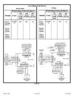
Страница 40: ...507029 03 Page 40 of 68 Issue 1622 Low Voltage Field Wiring Table 14 Single Stage 2 Stage...
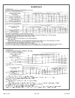
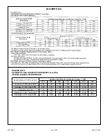
Страница 44: ...507029 03 Page 44 of 68 Issue 1622 BLOWER DATA...
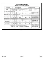
Страница 46: ...507029 03 Page 46 of 68 Issue 1622 Table 22 COOLING OPERATING SEQUENCE A97DSMV and Single Stage Outdoor Unit...
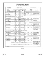
Страница 47: ...507029 03 Page 47 of 68 Issue 1622 Table 23 COOLING OPERATING SEQUENCE A97DSMV and Two Stage Outdoor Unit...
Страница 51: ...507029 03 Page 51 of 68 Issue 1622 Figure 50 Operation Signal Delta P Measurement Manifold Pressure Measurement...
Страница 57: ...507029 03 Page 57 of 68 Issue 1622...
Страница 58: ...507029 03 Page 58 of 68 Issue 1622...
Страница 59: ...507029 03 Page 59 of 68 Issue 1622...
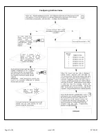
Страница 60: ...507029 03 Page 60 of 68 Issue 1622 Configuring Unit Size Codes...
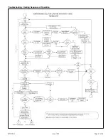
Страница 61: ...507029 03 Page 61 of 68 Issue 1622 Troubleshooting Heating Sequence of Operation...
Страница 62: ...507029 03 Page 62 of 68 Issue 1622 Troubleshooting Heating Sequence of Operation continued...
Страница 63: ...507029 03 Page 63 of 68 Issue 1622 Troubleshooting Heating Sequence of Operation continued...
Страница 64: ...507029 03 Page 64 of 68 Issue 1622 Troubleshooting Heating Sequence of Operation continued...
Страница 65: ...507029 03 Page 65 of 68 Issue 1622 Troubleshooting Cooling Sequence of Operation...
Страница 66: ...507029 03 Page 66 of 68 Issue 1622 Troubleshooting Continuous Fan Sequence of Operation...

