


507029-03
Page 55 of 68
Issue 1622
3.
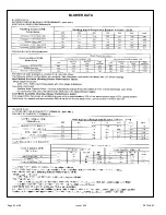
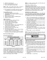
Check amp-draw on the blower motor with the b
l
ower
access panel in place.
Motor Nameplate
_____________
Actual
________
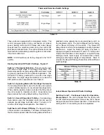
Winterizing and Condensate Trap Care
1.
Turn off power to the unit
.
2. Have a shallow pan ready to empty condensate water
.
3. Remove the drain cap from the condensate trap and
empty water
.
Inspect the trap then reinstall the drain
cap.
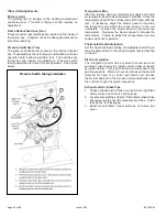
Cleaning Heat Exchanger
If cleaning the heat exchanger becomes necessary
,
follow the below procedures and refer to Figure 1 when
disassembling unit
.
Use papers or protective covering in
front of furnace while removing heat exchanger assembly
.
1.
Turn off electrical and gas supplies to the furnace
.
2. Remove the furnace access panels.
3. Disconnect the 2 pin plug from the gas valve
.
4.
Remove gas supply line connected to gas valve
.
Remove the burner box cover and remove gas valve
manifold assembly
.
5.
Remove sensor wire from sensor
.
Disconnect 2 pin
plug from the ignitor
.
6. Disconnect w
i
res from flame rollou
t
switches
.
7.
Remove four (4) burner box screws at the vestibule
panel and remove burner box
.
Set burner box assembly
aside
.
NOTE:
If necessary, clean burners at this time
.
Follow
procedures outlined in “Burner Cleaning” section
.
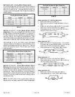
8. Loosen the clamps to the flexible exhaust coupling.
9. Disconnect condensate drain line from the cold end
header box.
10. Disconnect condensate drain tubing from flue collar.
Remove screws that secures the flue collar into place.
Remove flue collar. It may be necessary to cut the
exiting exhaust pipe for removal of the fitting.
11. Mark and disconnect all combustion air pressure tubing
from cold end header collector box.
12. Mark and remove wires from pressure switches.
Remove pressure switches. Keep tubing attached to
pressure switches.
13. Disconnect the 4 pin plug from the combustion air
inducer. Remove two screws which secure combustion
air inducer to collector box. Remove combustion air
inducer assembly. Remove ground wire from vest
panel.
14. Remove electrical junction box from the side of the
furnace.
15. Mark and disconnect any remaining wiring to heating
compartment components. Disengage strain relief
bushing and pull wiring and bushing through the hole
in the blower deck.
16. Remove the primary limit from the vestibule panel.
17. Remove two screws from the front cabinet flange at
the blower deck. Spread cabinet sides slightly to allow
clearance for removal of heat exchanger.
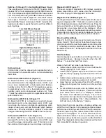
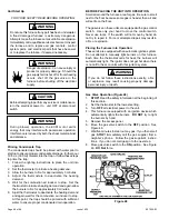
Service
At the beginning of each heating season
,
system should be
checked as follows by a qualified service technician
:
Blower
Check the blower wheel for debris and clean
i
f necessary.
The blower motors are p
r
elubricated for extended bearing
life
.
No further lubrication is needed
.
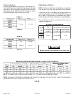
Filters
Al
l
filters are
i
nstalled external to the unit
.
Filters should
be inspected monthly
.
Clean or replace the filters when
necessary to ensure proper furnace operation. Table 3 lists
recommended filter sizes
.
Exhaust and Air Intake Pipes
Check the exhaust and air intake pipes and all connections
for tightness and to make sure there
i
s no blockage
.
NOTE:
After any heavy snow
,
ice or frozen fog event the
furnace vent pipes may become restricted
.
Always check
the vent system and remove any snow or ice that may be
obstructing the plastic intake or exhaust pipes
.
Electrical
1.
Check al
l
wiring for loose connections
.
2. Check for the correct voltage at the furnace (furnace
operating)
.
Correct voltage is /-10%.
Failure to follow safety warnings exact
l
y could result in
dangerous operation
,
serious injury
,
death or property
damage
.
Improper servicing could result in dangerous operation
,
serious injury
,
death
,
or property damage
.
Befo
r
e servicing
,
disconnect all electrica
l
powe
r
to
furnace
.
When servicing contro
l
s
,
label all wires prior to
disconnect
i
ng
.
Take care to reconnect w
i
res correctly
.
Verify proper operation after servicing
.
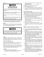
ELECTRICAL SHOCK, FIRE,
OR EXPLOSION HAZARD
WARNING
The blower access panel must be securely in place when
the blower and burners are operating
.
Gas fumes
,
which
could contain carbon monoxide, can be drawn into living
space resulting in personal injury or death
.
WARNING
Содержание A97DSMV
Страница 3: ...507029 03 Page 3 of 68 Issue 1622 A97DSMV Exploded View Figure 1...
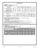
Страница 13: ...507029 03 Page 13 of 68 Issue 1622 OUTDOOR TERMINATION KITS USAGE Table 3...
Страница 17: ...507029 03 Page 17 of 68 Issue 1622 Table 5 Maximum Allowable Intake or Exhaust Vent Length feet...
Страница 24: ...507029 03 Page 24 of 68 Issue 1622 Figure 29...
Страница 27: ...507029 03 Page 27 of 68 Issue 1622 Figure 36 Trap Drain Assembly Using 1 2 PVC or 3 4 PVC...
Страница 33: ...507029 03 Page 33 of 68 Issue 1622 Figure 43 Typical A97DSMV Wiring Diagram...
Страница 34: ...507029 03 Page 34 of 68 Issue 1622 Figure 45...
Страница 35: ...507029 03 Page 35 of 68 Issue 1622 Figure 46...
Страница 36: ...507029 03 Page 36 of 68 Issue 1622 Figure 47 Integrated Control...
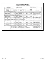
Страница 40: ...507029 03 Page 40 of 68 Issue 1622 Low Voltage Field Wiring Table 14 Single Stage 2 Stage...
Страница 44: ...507029 03 Page 44 of 68 Issue 1622 BLOWER DATA...
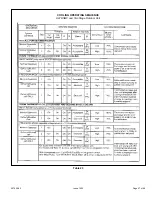
Страница 46: ...507029 03 Page 46 of 68 Issue 1622 Table 22 COOLING OPERATING SEQUENCE A97DSMV and Single Stage Outdoor Unit...
Страница 47: ...507029 03 Page 47 of 68 Issue 1622 Table 23 COOLING OPERATING SEQUENCE A97DSMV and Two Stage Outdoor Unit...
Страница 51: ...507029 03 Page 51 of 68 Issue 1622 Figure 50 Operation Signal Delta P Measurement Manifold Pressure Measurement...
Страница 57: ...507029 03 Page 57 of 68 Issue 1622...
Страница 58: ...507029 03 Page 58 of 68 Issue 1622...
Страница 59: ...507029 03 Page 59 of 68 Issue 1622...
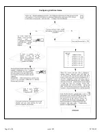
Страница 60: ...507029 03 Page 60 of 68 Issue 1622 Configuring Unit Size Codes...
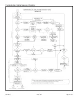
Страница 61: ...507029 03 Page 61 of 68 Issue 1622 Troubleshooting Heating Sequence of Operation...
Страница 62: ...507029 03 Page 62 of 68 Issue 1622 Troubleshooting Heating Sequence of Operation continued...
Страница 63: ...507029 03 Page 63 of 68 Issue 1622 Troubleshooting Heating Sequence of Operation continued...
Страница 64: ...507029 03 Page 64 of 68 Issue 1622 Troubleshooting Heating Sequence of Operation continued...
Страница 65: ...507029 03 Page 65 of 68 Issue 1622 Troubleshooting Cooling Sequence of Operation...
Страница 66: ...507029 03 Page 66 of 68 Issue 1622 Troubleshooting Continuous Fan Sequence of Operation...


