36
001
-005
53
-E
N
r
e
v. 5
Installing the scale
1)
Put new load cell in place, pass the wire within the boom and plug socket to scale display.
2)
Put the nylon washer in place and pass clevis pin through assembly.
3)
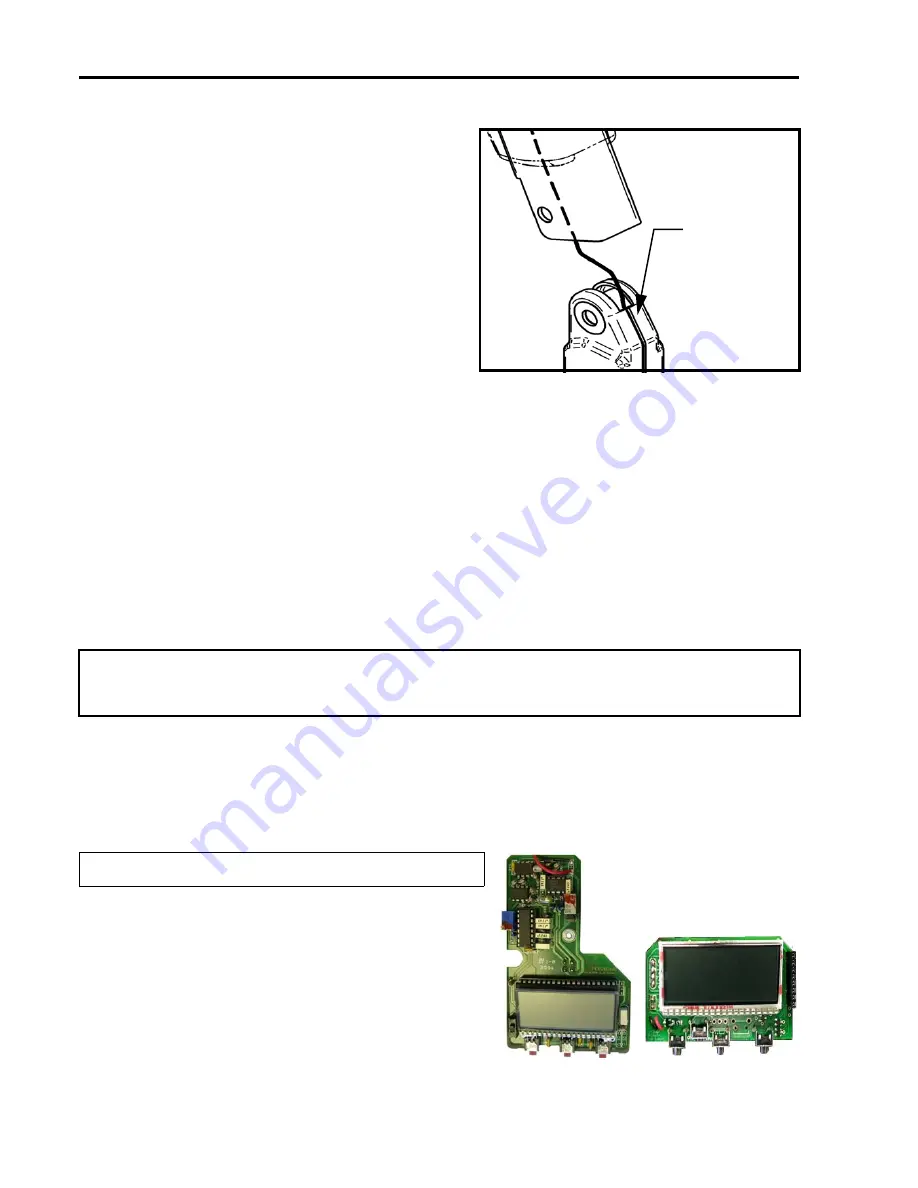
Install new cotter pin as shown in Fig. 32.
4)
Replace the boom end cap.
5)
Install the scale display. Do not over-tighten the screw passing through the center of the circuit;
too much torque could damage the board. Screw in the cover.
6)
Put the battery back in place.
7)
Calibrate and test the scale as per “Calibrating the Digital Scale” service procedure (SP19).
8)
Perform a safety working load test as per service procedure 22.
Service Procedure 19 - Calibrating the Digital Scale up to
and including SN 300155060
5)
Remove the load cell from the boom. Slide
back the boom end cap. If necessary, use
soap and water to ease displacement.
Remove the cotter pin from the clevis pin,
slide it out and dispose of it (see Fig. 32).
6)
Pull out load cell wire from boom.
7)
If necessary, remove the DPS or spreader
bar from the load cell as per “Service
Procedure 20 - Replacing the DPS/
SpreaderBar from the Load Cell”.
Fig. 34
Warning: If the scale or any other parts necessary to achieve the task are disassembled, it is
essential that all components are reinstalled correctly. If not, the consequence may be later
disengagement, which can lead to death or serious injury.
NOTE: From SN 300155061, see Scales (2016)
Technical Manual.
1)
The serial numbers for display and load cell must
be identical.
2)
Remove the screws from the back of the display
to expose the electronics. Identify the scale
version with the circuit board and proceed with
the relevent calibration process.
Calibrate as per
process #1
Calibrate as per
process #2
Warning:
Make sure
that the
inclined
surface of
the scale is
oriented as
shown.


