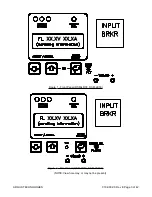
Micro-controller failure will cause the fan to go to high speed in the RSM-48/50 and RSM-24/100,
and to turn on in the RSM-48/30 and RSM-24/50. Fan operation is inhibited below -20 degrees
Celsius.
3.3.25
Battery Eliminator Operation
The unit maintains all specifications with or without a battery attached to the output. However if a
battery or another unit operating in parallel is not present the alarms will not be illuminated if the
A.C. power is removed. A minimum 5% load is required to avoid the rectifier fail alarm.
3.3.26
Remote or Local Sensing
The Module will regulate to a remote point when remote sense leads are connected to the “remote
sense” input. If the remote sense leads are not attached the units will automatically revert to internal
sensing. The internal sense point is at the output terminals.
3.3.27
Micro-controller Reset
In the unlikely event of a software glitch and the unit will not respond to local or remote action, the
unit is equipped with a hardware reset. A reset signal will be sent to the micro-controller by simul-
taneously holding down the Enter/Select key and turning the unit's A.C. input breaker off and on.
The micro-controller will restart at base code levels in the control software. Settings will not be al-
tered by this operation. The A.C. mains must be within limits to generate a reset pulse.
For the RSM 48/50 UPF and RSM 24/100 UPF series, one must reset the micro-controller by open-
ing the AC input circuit breaker, waiting 20 seconds, and then pressing the Enter/Select key and
turning the input breaker back on.
3.3.28
Output Voltage Test Points
Each module is equipped with test jacks to monitor the unit's output. The jacks are protected
against direct short circuit condition. Voltage is measured before the unit's output breaker.
3.3.29
Remote monitoring
All local controls and parameters are accessible via the Serial Communications Interface (optional).
Operators may monitor all of the units settings, alarm conditions and status via a modem. Please
see the Remote Access section for the terminal screens and technical parameters.
3.3.30
A.C. Inrush / Transient Suppression
The units' inrush current is limited to the nominal line current to prevent surges on the a line. Every
modules' input provides lightning and transient protection in accordance to IEEE standard 587 Class
B.
3.3.31
Control Fail Safe & Memory
All critical control functions utilize discrete programmable potentiometers to retain level settings. All
alarm set points are stored in nonvolatile memory. This approach enables retention of user level
programming during periods of inactivity such as transportion of the modules. Levels may also be
preset at a central service area before shipment to the field.
010-030-C0 Rev E Page 12 of 42
ARGUS TECHNOLOGIES


