3.3.08
Equalize Mode
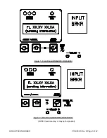
When the unit is required to equalize a battery string the EQUALIZE mode is generally used. This
mode can be entered manually via the front panel control or by an external signal supplied via the
external Equalize input. Holding down the Float/Equalize mode control button for three seconds
places the unit in the EQUALIZE mode. When in the EQUALIZE mode the output voltage of the
module is determined by the EQUALIZE VOLTAGE setting found in the submenu ADJUSTMENTS.
EQUALIZE
mode is indicated by illumination of the EQ beside the output voltage reading on the
LCD display. The level is protected by fail safe circuitry in the unlikely event of micro-controller fail-
ure.
3.3.09
Test Mode
The module is equipped with two Test modes, MANUAL or AUTO test. Either are selected under
the TEST sub menu.
3.3.09.1
Manual test
The output breaker must be in the Open position before this mode can be selected. The operator
will be prompted by the message OPEN O/P BREAKER if the breaker is closed. Selection of the
TEST
mode is via sub menu TEST. When in the MANUAL TEST mode the unit's alarm levels can
be checked with the output breaker open without disturbing the load if powered by a battery or par-
alleled modules. The simulated output voltage of the unit is set by the TEST adjustment Up and
Down
keys on the front panel. MANUAL TEST mode is indicated by MT beside the output voltage
reading on the LCD display. When the mode is exited the module returns to the previously selected
output mode ie. EQUALIZE.
3.3.09.2
Auto test - units without High Output Alarm feature:
AUTO TEST automatically ramps the unit's output to simulate a manual test. The auto process
starts with the output voltage at the programmed equalize level. This voltage is then decreased until
an under voltage alarm is generated. The output voltage and the low voltage alarm condition are
displayed simultaneously. After a three second hold period the voltage ramps up until the upper
level for the low voltage alarm is reached. The upper level is the lower level plus a hysterisis volt-
age (3 volts for a 48 volt system and 1.5 volts for a 24 volt system). After another 3 second hold
period the alarm message disappears and resumes an upward ramp up until the high voltage shut-
down circuit is activated. The message O/P H.V. SHUTDOWN will be displayed simultaneously with
the level. This level is held for three seconds before the unit exits out to the main menu for the test
mode. The H.V. shutdown does not require manual reset as it will restart automatically. AUTO
TEST
is aborted if the output breaker is closed during the process. When the mode is exited the
module will return to the previous output mode ie. FLOAT.
ARGUS TECHNOLOGIES
010-030-C0 Rev E Page 7 of 42


