3.0
General
3.1
Scope
This instruction manual covers the installation, and operation of Argus Technologies' RSM 48/100
switched mode rectifier.
3.2
Introduction
The RSM series of rectifiers employs a high frequency switched mode conversion technique to pro-
vide a fully regulated and isolated DC output from the A.C. mains. The unit provides external con-
nections for input, output and alarm interfaces. The 48 volt rectifiers are used in a positive ground
configuration only. The units are fully functional battery eliminators and therefore do not require an
external battery to meet the performance requirements as outlined in the specification section of this
manual.
3.3
Features
The following sections (3.3.01 through 3.3.32) will cover the various features available on the RSM
48/100 Rectifier.
3.3.01
LCD Display and Control Keys
Located on the front panel of the unit is a 2 row by 16 character LCD display. All of the unit's oper-
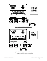
ating parameters, status and alarms can be viewed with this display See Figure #1 for a detail of a
normal display. Normally, the display indicates:
- Output current of the module
- Output voltage of the module
- Float/ Equalize /Test Mode Status
- Current limit or soft start indication
- Corporate identification, Module Serial #
NOTE: The front panel may be powered up for up to 20 seconds after all power (input and output)
is removed from the unit.
Float, equalize, soft start, current limit and test mode status designators pulsate to differentiate
them from the output voltage and current readings. The serial number is displayed with normal
mode, & alarm mode messages. The corporate identity is displayed only during normal operation.
Please see Figure #3 and Table #1 for the complete menu tree and display messages possible.
Possible alarm messages are referenced in the minor alarm section. The display is updated two to
three times per second. Output voltage and current are displayed on the top line under all modes of
operation. Current readings are accurate to within 2% while voltage measurements are accurate to
0.2%. Sensing for voltage and current measurements is present before the output breaker of the
module. Therefore only the true output of the rectifier is displayed. Refer to Figure #14 when per-
forming adjustments in order to see how the front panel message display changes when accepting
input.
There are three control buttons on the front panel and are labelled with an up arrow, down arrow,
and a curved arrow. The first two (ADJUST/SCROLL) are used to scroll thru a list of items in for-
ward and reverse order, and the last button (ENTER/SELECT) is used to select the displayed item.
Initially the ADJUST/SCROLL buttons allow the user to change the display from its normal Volt-
age/Current/Alarms mode (NORMAL) to one of STATUS, ADJUSTMENTS, REMOTE COMMUNI-
CATIONS
, or TEST MODE and the third button is used to switch between FLOAT and EQUALIZE
modes when the display is in the NORMAL mode.
010-030-C0 Rev E Page 2 of 42
ARGUS TECHNOLOGIES


