19
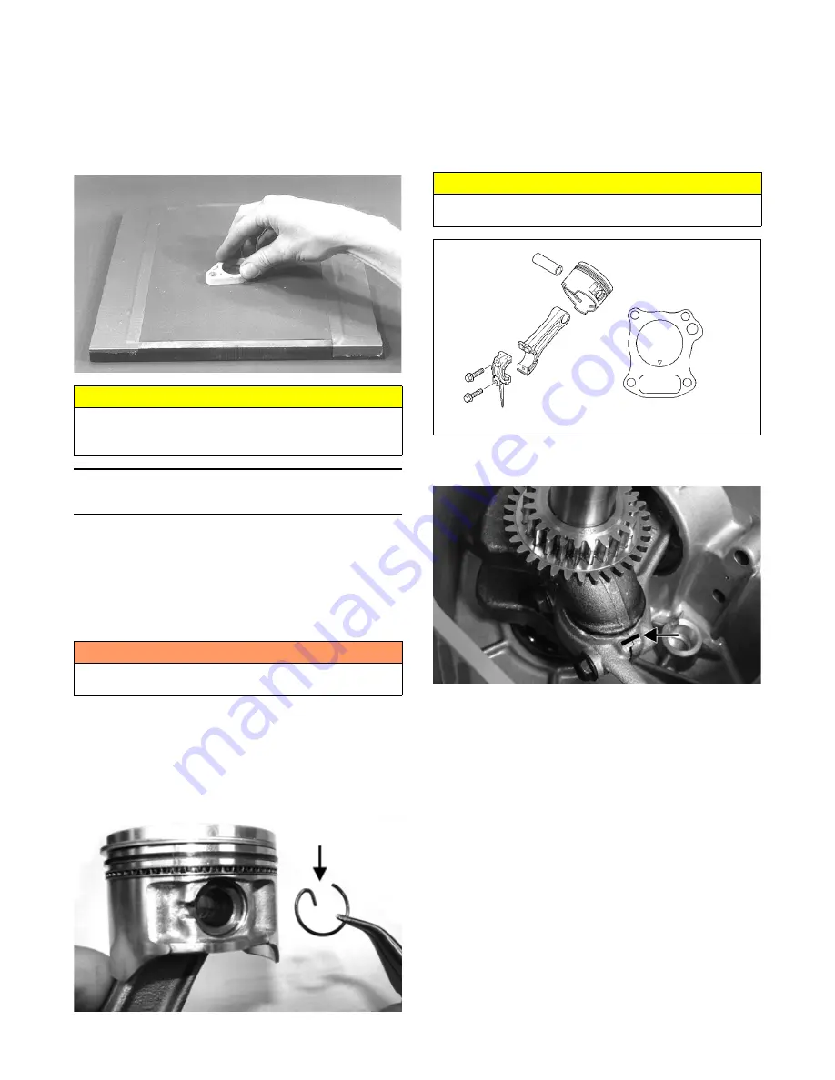
2. Inspect the sealing surfaces for trueness by placing
each on the surface plate covered with #400 grit wet-
or-dry sandpaper. Using light pressure, move both
sides in a figure eight motion. Inspect the sealing
surfaces for any indication of high spots or warping.
Correct highs spots by continuing to move each side
in a figure eight motion. Warped components must
be replaced.
A932
Assembling
NOTE: The use of new gaskets and seals is recom-
mended when assembling the engine.
NOTE: Prior to assembling the engine, use parts
cleaning solvent and compressed air and thoroughly
clean the threaded holes of the crankcase and cylinder
and head to properly tighten.
NOTE: When the use of a lubrication is indicated,
use clean engine oil.
1. Lubricate the piston pin, connecting rod, and piston
pin bore with engine oil; then install the piston to the
connecting rod and secure the piston pin with the cir-
clips directed either up or down.
IO091A
NOTE: Coat the cylinder wall, connecting rod bear-
ing surface, and the crankshaft with engine oil.
2. Install the crankshaft into the crankcase; then with
the piston rings properly oriented (end gap 120°
apart), compress the piston rings and install the pis-
ton and connecting rod assembly taking care not to
damage the crankshaft and connecting rod.
0745-001
3. Note the marks on the connecting rod and end cap
made during disassembly.
IO081A
NOTE: When installing the connecting rod to the
crankshaft, rotate the crankshaft so the rod journal is
in the six o’clock position to allow access for installing
the rod end cap.
4. With the connecting rod, end cap, and crankshaft
journal lubricated with engine oil, install the con-
necting rod and rod end cap to the crankshaft and
secure with the cap screws. Tighten evenly to 106
in.-lb.
CAUTION
Water or parts-cleaning solvent must be used in con-
junction with the wet-or-dry sandpaper or damage to
the sealing surfaces may result.
! WARNING
Always wear safety glasses when drying components
with compressed air.
CAUTION
The arrow of the piston must be directed towards the
push rod opening of the cylinder.
Содержание ZR 120
Страница 1: ...2017 S SERVICE ERVICE MANUAL ANUAL www arcticcat com...
Страница 44: ...43...
Страница 60: ...59 Wiring Diagram 0750 506...
Страница 61: ...60 NOTES...
Страница 62: ...Printed in U S A Trademarks of Arctic Cat Inc Thief River Falls MN 56701 p n 2261 697...


