59
729-325A
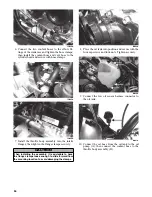
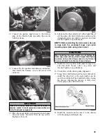
5. Connect the wiring harness to the injectors making
sure the number 1 harness is connected to the
MAG-side injector.
Testing Ignition Timing Sensor
Resistance
0729-627
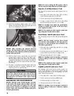
NOTE: This sensor is located inside the magneto
case next to the flywheel, and the recoil starter and
the flywheel must be removed to access the sen-
sor.
1. Disconnect the sensor connector (green/white and
brown/green) from the ECU.
2. Set the selector in the OHMS position; then con-
nect the meter leads to the sensor leads.
3. Sensor resistance must be 101 ohms ± 20%.
Electric Fuel Pump
1. Remove the hardware securing the console to the
gas tank and frame; then move the console out of
the way.
2. Disconnect the fuel pump from the main wiring
harness.
3. Connect the positive lead of a 12-volt power sup-
ply to the red wire and the negative lead of the 12-
volt power supply to the black wire.
4. The pump should operate (it would be heard run-
ning).
NOTE: If the fuel pump fails to operate, the pump
is defective and must be replaced.
Fuel Pressure Regulator
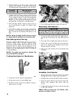
1. Using the Fuel Pressure Test Kit, connect the tes-
ter to the delivery pipe and gasline hose.
AO053
NOTE: A short piece of 3/8 in. I.D. hose will be
needed for this procedure.
2. Pressurize the regulator to 2.0-2.2 kg/cm² (28-31.3
psi). Turn the pressure tester shut off valve to the
OFF position. Observe the gauge for several min-
utes and note any loss of pressure. If pressure
begins to drop, the cause may be a ruptured dia-
phragm, worn spring, or leaking valve. If the regu-
lator fails to build or maintain pressure, the fuel
pump assembly must be replaced.
NOTE: If the pressure drops, check the hose con-
nections to ensure no leaks exist.
Testing Coolant Temperature
Sensor Resistance
NOTE: The coolant temperature sensor is very
sensitive to temperature change. Before the resis-
tance test is conducted, the coolant temperature
must be known. If the engine has been operated
recently and the coolant is warm, the resistance
will measure lower than if the coolant was at room
temperature or colder. For accurate test results,
check the coolant temperature in the filler neck
using a thermometer.
1. Disconnect the coolant temperature sensor wiring
harness from the main harness.
2. Set the meter selector to the OHMS position and
test the resistance between the two leads from the
sensor.
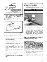
CAUTION
The fuel supply hose may be under pressure. Place an
absorbent towel around the connection to absorb fuel;
then remove the hose slowly to release the pressure.
Содержание 500 Sno Pro
Страница 1: ...TM SHARE OUR PASSION Operator s Performance Manual Performance Manual 500 Sno Pro...
Страница 2: ......
Страница 6: ...NOTES...
Страница 22: ...16 NOTES...
Страница 68: ...62 NOTES...
Страница 92: ...86 NOTES...
Страница 93: ...87 NOTES...
Страница 94: ...88 NOTES...
Страница 95: ...Printed in U S A Trademarks of Arctic Cat Inc Thief River Falls MN 56701 p n 2258 721...


