background image

8

Chain Case 

Performance 

Calibrations

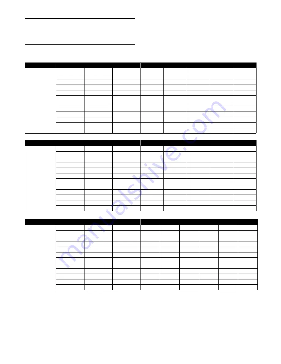
NOTE: The following table should be used as a guide only.

RPM x Ratio x 0.0225 x 1.12 = MPH

RPM x Ratio x 0.0213 x 1.12 = MPH

RPM x Ratio x 0.02368 x 1.12 = MPH

*Production

NOTE: The above gearing options are combinations which allow acceptable chain tension. Any other

combinations will not allow acceptable chain tension.

Drive Sprocket

Chain Case Performance Specifications

RPM (Engine)

8-Tooth

(3.00 Pitch)

Sprockets

Ratio

Chain Pitch

7400

7800

8000

8200

8700

20/46

0.435

74

81.1

85.5

87.7

89.9

95.4

20/45

0.444

74

82.8

87.3

89.5

91.7

97.3

21/45

0.467

74

87.1

91.8

94.1

96.5

102.4

19/40

0.475

70

88.6

93.4

95.8

98.2

100.5

21/41

0.512

72

95.5

100.6

103.2

105.8

112.3

20/39

0.513

70

95.7

100.8

103.4

106.0

112.5

22/41

0.537

72

100.1

105.5

108.2

110.9

113.6

22/40

0.550

72

102.6

108.1

110.9

113.7

120.6

23/40

0.575

72

107.2

113.0

115.9

118.8

121.7

23/39

0.590

72

110.0

116.0

119.0

121.9

129.4

24/39

0.615

72

115.0

120.9

124.0

127.1

134.8

Drive Sprocket

Chain Case Performance Specifications

RPM (Engine)

9-Tooth

(2.52 Pitch)

Sprockets

Ratio

Chain Pitch

6000

7000

8000

9000

10,000

20/46

0.435

74

62.3

72.6

83.0

93.4

103.8

20/45

0.444

74

63.6

74.1

84.7

95.3

105.9

21/45

0.467

74

66.8

78.0

89.1

100.3

111.4

19/40

0.475

70

68.0

79.3

90.7

102.0

113.3

21/41

0.512

72

73.3

85.5

97.7

109.9

122.1

20/39

0.513

70

73.4

85.7

97.9

110.1

122.4

22/41

0.536

72

76.7

89.5

102.3

115.1

127.9

22/40

0.550

72

78.7

91.8

105.0

118.1

131.2

23/40

0.575

72

82.3

96.0

109.7

123.5

137.2

23/39

0.590

72

84.5

98.5

112.6

126.7

140.8

24/39

0.615

72

88.1

102.7

117.4

132.1

146.7

Drive Sprocket

Chain Case Performance Specifications

RPM (Engine)

10-Tooth*

(2.52 Pitch)

Sprockets

Ratio

Chain Pitch

7400

7800

8000

8200

8400

8700

20/46*

0.435

74

85.4

90.0

92.3

94.7

97.0

100.4

20/45

0.444

74

87.1

91.8

94.2

96.6

99.0

102.4

21/45

0.467

74

91.6

96.6

99.1

101.6

104.1

107.8

19/40

0.475

70

93.2

98.3

100.8

103.3

105.8

109.6

21/41

0.512

72

100.5

105.9

108.6

111.3

114.1

118.1

20/39

0.513

70

100.7

106.1

108.8

111.6

114.3

118.4

22/41

0.537

72

105.3

111.0

113.8

116.7

119.5

123.8

22/40

0.550

72

108.0

113.8

116.7

119.6

122.5

126.9

23/40

0.575

72

112.8

118.9

122.0

125.0

128.1

132.7

23/39

0.590

72

115.8

122.0

125.2

128.3

131.4

136.1

24/39

0.615

72

120.7

127.2

130.5

133.7

137.0

142.0

Содержание 500 Sno Pro

Страница 1: ...TM SHARE OUR PASSION Operator s Performance Manual Performance Manual 500 Sno Pro...

Страница 2: ......

Страница 3: ...n storage instructions If major repair or service is ever required contact an authorized Arctic Cat Snowmobile dealer for professional ser vice At the time of publication all information and illustrat...

Страница 4: ...nced operator Never accelerate rapidly or drive at high speed beyond the limits of visi bility or without being totally familiar with the terrain and what lies in front of you Obey speed limits and ne...

Страница 5: ...way Bar 18 Track Tension Track Alignment 18 Ski Alignment 19 Handlebar Alignment 21 Handlebar Height Adjustment 21 Steering Speed Ratio Adjustment 22 Drive Belt 22 Hydraulic Brake System 23 Recommende...

Страница 6: ...NOTES...

Страница 7: ...End Play 0 002 0 004 in Reed Stopper Height 0 315 in Chassis Length Overall 296 6 cm 116 8 in Height Overall 115 5 cm 45 5 in Width Overall 125 2 cm 49 3 in Ski Center to Center Distance Stance 109 9...

Страница 8: ...1 9 23 31 3 48 65 3 73 99 3 98 133 3 24 32 6 49 66 6 74 100 6 99 134 6 25 34 50 68 75 102 100 136 Type of Bolt Thread Diameter A mm Tightening Torque Grade 8 8 5 60 in lb 6 96 in lb 8 20 ft lb 10 40 f...

Страница 9: ...44 111 0 857 977 42 108 0 906 1041 40 104 0 955 1105 38 100 1 023 1214 36 97 1 091 1323 34 93 1 159 1432 32 90 1 227 1541 30 86 1 295 1650 TEMP C TEMP F VOLTAGE OHMS 28 82 1 377 1800 26 79 1 459 1950...

Страница 10: ...07 4285 42 108 0 754 4630 40 104 0 802 4975 38 100 0 869 5490 36 97 0 937 6005 34 93 1 004 6520 32 90 1 072 7035 30 86 1 139 7550 TEMP C TEMP F VOLTAGE OHMS 28 82 1 230 8540 26 79 1 322 9530 24 75 1 4...

Страница 11: ...ation note that Arctic Cat has called out three check points at either end out on the taper as shown and also on the center bearing race The crankshaft is still supported on the outer bearings using V...

Страница 12: ...BRACKET P N Length Width PITCH P N DEGREE 500 Sno Pro 0627 047 45 41 in 1 41 in 3500 6000 20 46 15 wide 74 15 wide 1602 774 40 38 Drive Clutch Spring Color Spring Rate Cam Arm Grams 0646 400 Blue Tita...

Страница 13: ...746 689 69 0 0746 527 50 5 0746 605 52 0 0746 690 47 0 0746 529 49 5 0746 606 48 4 0746 691 44 0 0746 531 44 5 0746 607 46 0 0746 692 50 0 0746 533 47 5 0746 608 47 5 0746 694 63 0 0746 534 51 5 0746...

Страница 14: ...Tooth 2 52 Pitch Sprockets Ratio Chain Pitch 6000 7000 8000 9000 10 000 20 46 0 435 74 62 3 72 6 83 0 93 4 103 8 20 45 0 444 74 63 6 74 1 84 7 95 3 105 9 21 45 0 467 74 66 8 78 0 89 1 100 3 111 4 19...

Страница 15: ...Chain NUMBER OF TEETH INSIDE SPLINE P N 19 15 1602 412 20 15 1602 413 21 15 2602 215 22 15 2602 244 23 15 2602 216 24 15 2602 254 39 15 1602 414 39 16 2602 217 40 15 1602 415 40 16 2602 245 40 16 2602...

Страница 16: ...iameter 4639 962 2603 804 12 7 mm diameter 4639 963 2603 775 14 3 mm diameter Part No Free Length Rate lb in Active Coils Total Coils 2703 385 13 00 in 175 8 50 10 50 2703 386 13 00 in 160 8 00 10 00...

Страница 17: ...0 x 0 093 in Backup washer 0 900 x 0 008 in 0 800 x 0 008 in Piston Orifice 0 035 in Piston Depth 2 63 in 1 125 x 0 093 in Top out washer Part Number Description Compression Piston Side Rebound Piston...

Страница 18: ...0603 350 Valve 1 300 OD X 0 377 ID X 0 010 TH 0603 891 Valve 1 300 OD X 0 377 ID X 0 012 TH 0603 890 Valve 1 300 OD X 0 377 ID X 0 015 TH 2603 902 Valve 0 550 OD X 0 377 ID X 0 020 TH AC PN Descripti...

Страница 19: ...74 52 2 04724 03 00118 53 02087 3 11811 53 2 08661 04 00157 54 02126 4 15748 54 2 12598 05 00197 55 02165 5 19685 55 2 16535 06 00236 56 02205 6 23622 56 2 20472 07 00276 57 02244 7 27559 57 2 24409 0...

Страница 20: ...ram Hood Harness p n 1686 587 NOTE At the time of publication the Hood Harness p n 1686 587 diagram was not available however the diagram will be available in the near future from your Arctic Cat Snow...

Страница 21: ...tion Main Harness p n 1686 585 NOTE At the time of publication the Ignition Main Harness p n 1686 585 diagram was not available however the diagram will be available in the near future from you Arctic...

Страница 22: ...16 NOTES...

Страница 23: ...and install the windshield O rings 2 4 With the windshield in place install the reinstall able rivets 3 and press each rivet until it locks into place INSTALLING SPINDLE A ARM 743 066B 1 Install the...

Страница 24: ...5 8 cm 2 3 in off the floor 2 At mid point of the track on the bottom side hook a spring scale around a track clip then pull down on the scale to 9 kg 20 lb Measure the deflection distance between the...

Страница 25: ...ment Ski alignment must be performed on a flat level surface Ski toe out must fall within the specified range 1 Raise the front end of snowmobile just high enough that the ski shocks are fully extende...

Страница 26: ...edge Adjusting NOTE The following procedure can be used to adjust the alignment of either ski 1 Unlock the steering tie rod by loosening the jam nuts A NOTE The inside jam nuts are left hand thread C...

Страница 27: ...to the steering support bracket 743 092A 4 To move the right side handlebar forward tap the steering post mount plate to the left 5 To move the left side handlebar forward tap the steering post mount...

Страница 28: ...h to install the drive belt 743 067A 3 Place the belt so the part number can be read between the sheaves of the drive clutch 4 With the sheaves fully apart roll the belt over the stationary sheave 5 W...

Страница 29: ...E Please advise the customer when taking delivery of the snowmobile that for optimum per formance not to exceed the recommended 87 octane gasoline Using a higher octane gasoline will not increase over...

Страница 30: ...VIN is stamped on the top of the tunnel The Engine Serial Number ESN is stamped into the crankcase of the engine 0744 098 These numbers are required by the dealer to complete warranty claims properly...

Страница 31: ...improve the total performance of the engine If any exhaust system component is removed from the engine and the engine is run severe engine damage will result AIR INTAKE SILENCER Used in conjunction w...

Страница 32: ...e dealer for this service DRIVE CLUTCH DRIVEN PULLEY ALIGNMENT The parallelism and the offset between the drive clutch and driven pulley are set at the factory Normally no adjustment is necessary as l...

Страница 33: ...e correct fuel mixture and timing for optimum operation EFI Features 1 Automatic compensation for temperature 2 Automatic compensation for altitude 3 Optimum throttle response through high pressure in...

Страница 34: ...ng all accesso ries and the lighting system Air Temperature Sensor This sensor detects air temperature entering the air silencer and engine The ECU sends current to this sensor and depending on the te...

Страница 35: ...Each shock absorber should be visibly checked daily for excessive fluid leakage cracks or breaks in the lower case a bent plunger and wear or leakage in the hoses If any one of these conditions is de...

Страница 36: ...or pull the tether switch cap off the tether switch BRAKING Operating a snowmobile with hydraulic brakes is dif ferent from operating a snowmobile with mechanical brakes The following items are items...

Страница 37: ...terial and extends the life of the pads EMERGENCY STOPPING There are several methods of stopping or slowing the snowmobile under a variety of situations Identified in the following chart are the ways...

Страница 38: ...also be greased after trailering the snowmobile on an open trailer Pump grease into the grease fittings and wipe excess grease from the bellcrank 0744 878 REAR SUSPENSION 1 Shut engine off and wait fo...

Страница 39: ...I Replace brake hose every year Brake Pads I I I Inspect for wear Throttle Cable Lever I I I Inspect for proper adjustment and wear Fuel Hoses I I I Inspect for wear and pinching Replace yearly Exhaus...

Страница 40: ...to service top side components the engine does not have to be removed from the chassis 1 Remove the upper cap screw securing the expan sion chamber to the upper spar then remove the springs and hairp...

Страница 41: ...ven pulley and the drive belt RS068 5 Remove the cap from the coolant filler neck then using Vacuum Test Pump p n 0644 131 or a suit able substitute drain the engine coolant 6 Remove the cable ties se...

Страница 42: ...the way IO041A NOTE The intake boot must be compressed enough to allow room to move the throttle body assembly forward and out of the intake flanges IO042 10 Remove the clamp from the vent hose then l...

Страница 43: ...of the chassis and account for the engine mount spacer A located between the MAG side and PTO side engine mounting bracket then with the engine removed remove the cap screws securing the engine mount...

Страница 44: ...to the side to access the Phillips head cap screw securing the stator lead wire then remove the cap screw FC018 6 Remove the stator plate from the engine FC021 FC065 NOTE The stator plate screws had...

Страница 45: ...h pistons NOTE For proper assembly keep all MAG side components and all PTO side components sepa rated Assemble them on their proper sides FC029 13 Lift the pistons clear of the connecting rods and re...

Страница 46: ...ase halves 21 Separate the crankcase halves by installing two crankcase cap screws in opposite corners leaving the heads approximately 6 mm 1 4 in out Using a plastic hammer and lifting on the ends of...

Страница 47: ...ked or damaged in any way replacement is necessary Cylinder Head 1 Using a non metallic carbon removal tool remove any carbon buildup from the combustion chambers being careful not to nick scrape or d...

Страница 48: ...clean car bon from the ring grooves Be sure to position the ring with its tapered side up 3 Inspect each piston for cracks in the piston pin and skirt areas 4 Inspect each piston for seizure marks or...

Страница 49: ...for that service 1 Wash the crankshaft with bearings in parts clean ing solvent 2 Inspect the bearings for wear scoring scuffing damage or discoloration Rotate the bearings Bearings must rotate freel...

Страница 50: ...the screws tightened to 48 in lb CM164A Measuring Critical Components NOTE Critical engine specifications charts can be found in Section 1 of this manual Cylinder Head Volume Squish Gap Method To chec...

Страница 51: ...back about 1 in from the bottom of each cylinder 2 Measure the corresponding piston skirt diameter at a point 1 cm above the piston skirt at a right angle to the piston pin bore Subtract this measurem...

Страница 52: ...shaft Runout Repair Specifications in Section 1 of this manual 3 Position the indicator contact point against the crankshaft location point B MAG end from the crankshaft end Zero the indicator and rot...

Страница 53: ...sitioned inward NOTE The bearing retaining pin hole is the hole that doesn t go entirely through the bearing case CM043A 7 Lubricate the inner lips of the crankshaft oil seals with grease then slide t...

Страница 54: ...m cap screws to 96 in lb and the ten 10 mm cap screws in two steps from 13 ft lb to 37 ft lb using the pattern shown 0738 201 NOTE After tightening the crankcase turn the engine right side up and tigh...

Страница 55: ...hin coat of grease to the seal outer surface CM169 19 Place the impeller into position and secure with a cap screw and washer Be sure the rubber side of the washer is lubricated with a light coat of g...

Страница 56: ...l the cover Secure with six screws then using the pattern shown tighten to 96 in lb NOTE Lubricating the O ring with a light coat of grease will help keep the O ring in place FC134 0742 304 22 Noting...

Страница 57: ...or down CM195B NOTE To aid in the circlip installation install the circlip to the inside of the piston before installing the connecting rod 29 Rotate each piston ring until the ring ends are properly...

Страница 58: ...finger tighten all four cap screws while observing the cylinder O rings to make sure they remain in position Slowly place the head into position on top of the O rings Start and finger tighten the rema...

Страница 59: ...e 1 With the spacer A and related cap screws prop erly oriented install the lower MAG side and PTO side engine brackets to the crankcase then install the left side mounting bracket to the mag neto hou...

Страница 60: ...flange clamps securely IO043A 8 Place the oil tank into position and secure with the four cap screws and lock nuts Tighten securely IO036A 9 Connect the low oil sensor harness connector to the oil tan...

Страница 61: ...n using a clean towel 15 Install the driven pulley with inner O ring key and stub shaft Secure with a cap screw and washer Tighten to specifications 16 Check drive clutch driven pulley alignment 17 Us...

Страница 62: ...er must show 15 2 22 8 ohms NOTE If reading is not within the specification recheck to confirm test results If still out of toler ance replace the stator NOTE If the resistance test is good a peak rea...

Страница 63: ...NOTE A throttle body assembly with the same symbol marking on the injectors as the ones being replaced must be ordered The symbol is located on the side of the injector top Testing Throttle Position S...

Страница 64: ...age NOTE The engine will continue to operate this way until the TPS is replaced Testing Fuel Injector Resistance IO031 1 Disconnect the fuel injector wiring harness 2 Set the meter selector to the OHM...

Страница 65: ...short piece of 3 8 in I D hose will be needed for this procedure 2 Pressurize the regulator to 2 0 2 2 kg cm 28 31 3 psi Turn the pressure tester shut off valve to the OFF position Observe the gauge f...

Страница 66: ...push pins 2 Connect the wiring harness to the air temperature sensor Secure the sensor leads with cable ties so they do not rub on any other components Removing Throttle Body NOTE The expansion chambe...

Страница 67: ...ver shaft 3 Remove the E clip securing the oil injection cable to the oil injection pump control arm Account for a washer 4 Loosen the oil injection cable jam nuts 5 Remove the handlebar pad 6 Remove...

Страница 68: ...62 NOTES...

Страница 69: ...check valve and gasket 3 Position the oil injection pump on the engine mak ing sure the oil injection pump gear is correctly aligned with the oil injection pump drive gear 4 Secure the pump with two...

Страница 70: ...tool and the hose to allow air in the hose to escape 4 Fill the usage tool with recommended oil to the 0 line 5 Wipe the tip of the tool to remove excess oil then attach the tool to the oil supply hos...

Страница 71: ...rrect gap is 0 7 0 8 mm 0 028 0 031 in Checking Spark Plugs To check spark plug condition and to aid in determin ing correct fuel air mixture pull the spark plug caps off the spark plugs remove the sp...

Страница 72: ...be checked every time before starting the engine The brake fluid must be maintained at a level just below the high mark on the reservoir BRAKE FLUID Checking Adding Brake Fluid 1 With the reservoir in...

Страница 73: ...e checked daily and changed if worn or damaged To check and change the brake pads use the following procedure 1 Measure the width of both brake pads The brake pad width must be greater than 3 2 mm 0 1...

Страница 74: ...starting the snowmobile in extremely cold tem peratures the drive belt should be removed and warmed up to room temperature Once the drive belt is at room temperature install the drive belt Also drive...

Страница 75: ...y purposes and are not designed to depict actual conditions Disassembling 1 Remove the spacers and O rings from the eyelets 2 Clean the entire shock assembly with soapy water Dry the shock assembly wi...

Страница 76: ...from the vise and clean all internal components then set body assembly aside on a clean lint free rag or towel 15 Clamp the shaft eyelet securely in vise with the piston end up 16 Remove the piston l...

Страница 77: ...with the dished side directed down 13 Using an appropriate measuring device set the IFP depth at 2 78 in FS283 14 Lubricate and replace the IFP bleed screw O ring then while holding the IFP with a dep...

Страница 78: ...correct taillight brakelight bulb is p n 0409 056 The correct headlight bulbs are p n 0409 073 and 0409 045 Removing and Installing Taillight Brakelight Bulb 1 Remove the screws securing the taillight...

Страница 79: ...used to protect the finish on the hood and belly pan NOTE Prior to tipping the snowmobile on its side apply the brake and set the brake lever lock NOTE When laying the snowmobile on its left side pro...

Страница 80: ...following procedure 1 Clean the seat cushion with a damp cloth and Arc tic Cat Vinyl Protectant p n 0636 173 2 Clean the snowmobile thoroughly by hosing dirt oil grass and other foreign matter from t...

Страница 81: ...deterioration or cracks replace if necessary Make sure all connections are tight 6 Inspect the entire brake system fluid level pads etc all controls headlight taillight brakelight ski alignment ski we...

Страница 82: ...83 8 mm Cap Screw Usage Pull flywheel off crankshaft on all Arctic Cat 2 stroke models 0744 040 Product Container Size Part Number Pkg Qty Synthetic APV 2 Cycle Oil 55 gal 2639 509 1 Synthetic APV 2 C...

Страница 83: ...0644 328 Complete Set p n 0643 073 Extractor Nut Only Small p n 0643 074 Extractor Nut Only Medium p n 0643 075 Extractor Nut Only Large p n 0643 072 Threaded T Handle Usage Remove piston pins 0644 32...

Страница 84: ...Remove install crankcase water pump bearings and seals 0644 502 Compression Tester Kit p n 0444 213 Complete Kit p n 0444 207 10 mm Adapter p n 0444 093 12 mm Adapter Usage Test cylinder compression...

Страница 85: ...404 5 8 in O D x 3 8 in I D p n 0644 542 5 8 in O D x 1 2 in I D Usage Protect cap seal on rebuildable shock absorbers 0644 404 Clutch Compressor p n 0644 420 Usage Compress and hold drive clutch in...

Страница 86: ...ble assemble Arctic ACT and Team Industries roller driven pulleys 0644 444 Spider Removal Kit p n 0644 449 Complete Kit p n 0744 037 Handle p n 0744 036 Removal Tool p n 0644 380 Clutch Holder 33 mm p...

Страница 87: ...mplete Kit 6 in p n 0644 400 Complete Kit 8 in p n 0644 114 A Handle 6 in p n 0644 401 A Handle 8 in p n 0644 111 B Insertion Tool p n 0644 120 C Pivot Plate p n 0644 118 D Adapter Plate Smaller I D p...

Страница 88: ...3 Inflation Needle p n 0744 020 Usage Pressurize rebuildable gas shock absorbers with nitrogen 0744 020 Inflation Needle Replacement p n 0644 162 Usage Replacement needle assembly for Inflation Nee dl...

Страница 89: ...ove rear suspension springs 0144 311 Hex Bits 1 4 in Hex Drive p n 0644 317 5 mm p n 0644 316 6 mm Usage With Quick Disconnect Coupler p n 0644 308 remove and install bolts and screws 0644 316 Insert...

Страница 90: ...0623 874 8 32 p n 0623 529 779 10 32 Usage With Rivnut Tool p n 0644 232 replace rivnuts 0623 557 Rivnut Tool p n 0644 232 Usage Collapse and install rivnuts 0644 232 Toggle Switch Wrench p n 0644 566...

Страница 91: ...Usage Drive 3 8 in square drive sockets 0644 021 Torx Bit Insert 5 16 in Hex Drive p n 0644 314 Usage With Insert Holder p n 0644 315 remove and install torx head screws 0644 314 Torx Bits 1 4 in Hex...

Страница 92: ...86 NOTES...

Страница 93: ...87 NOTES...

Страница 94: ...88 NOTES...

Страница 95: ...Printed in U S A Trademarks of Arctic Cat Inc Thief River Falls MN 56701 p n 2258 721...

Отзывы: