56
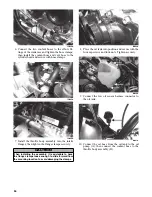
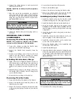
IO033A
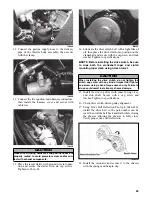
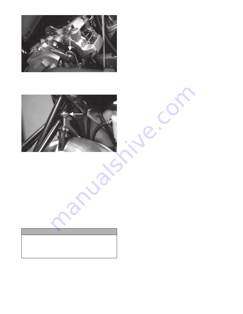
19. Install the expansion chamber and secure with the
springs; then install the link to the upper spar with
cap screw and tighten to 96 in.-lb.
IO032A
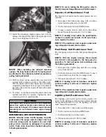
NOTE: When installing the exhaust manifold
springs, the long hook portion of the spring must
be attached to the exhaust manifold or premature
spring failure will result.
20. With the front of the snowmobile elevated, add
coolant until coolant is visible at the filler neck.
Start the engine and run the engine up to operating
temperature and inspect for any signs of coolant or
gas leaks; then turn the engine off and add coolant
if necessary.
21. Test drive or run the snowmobile and recheck the
coolant level after 5-6 minutes. Tighten the drive
clutch cap screw to specifications.
INDIVIDUAL EFI COMPONENTS
NOTE: With the Arctic Cat EFI System, the ECU
must receive the proper current output from four
coils (two charge coils, an injector coil, and a fuel
pump coil) to function as designed. If a problem
exists, these coils should be checked using the
following procedures.
NOTE: To aid in testing the EFI system, refer to
the EFI Analyzer Usage Manual with EFI Analyzer.
Injector Coil Resistance Test
The injector coil located on the stator powers the two
injectors.
1. Disconnect the double-wire plug with two blue/
white leads from the stator to the ECU.
2. Set the meter selector to the OHMS scale.
3. Connect a meter lead to each of the blue/white
leads. The meter must show 15.2-22.8 ohms.
NOTE: If reading is not within the specification,
recheck to confirm test results. If still out of toler-
ance, replace the stator.
NOTE: If the resistance test is good, a peak read-
ing voltage test should also be made.
Fuel Pump Coil Resistance Test
The fuel pump coil powers the fuel pump through the
ECU.
NOTE: With the engine running, there should
12.3-12.9 DC volts supplied to the fuel pump for
operation. To test fuel pump coil resistance, use
the following procedure.
1. Disconnect the double-plug with the two orange
wires from the ECU.
2. Set the meter selector to the OHMS scale. Connect
a meter lead to each of the two orange leads.
3. The meter must show 1.52-2.28 ohms.
NOTE: If reading is out of tolerance, recheck to
confirm reading. If still out of tolerance, replace
the stator.
NOTE: If the resistance test is good, a peak read-
ing voltage test should also be made.
Lighting Coil Resistance Test
The lighting coil located on the stator provides AC
power to the lighting system and accessories through
the regulator/rectifier. To test the lighting coil resis-
tance, follow this procedure.
1. Disconnect the 3-wire connector at the engine.
2. Set the meter selector to the OHMS scale.
3. Test between the two yellow leads.
4. The meter must show 0.08-0.12 ohm.
NOTE: If reading is out of tolerance, recheck to
confirm reading. If still out of tolerance, replace
the stator.
CAUTION
If the engine had a major overhaul or if any major com-
ponent was replaced, proper engine break-in proce-
dures must be followed. If the proper engine break-in
procedures are not followed, severe engine damage
may result.
Содержание 500 Sno Pro
Страница 1: ...TM SHARE OUR PASSION Operator s Performance Manual Performance Manual 500 Sno Pro...
Страница 2: ......
Страница 6: ...NOTES...
Страница 22: ...16 NOTES...
Страница 68: ...62 NOTES...
Страница 92: ...86 NOTES...
Страница 93: ...87 NOTES...
Страница 94: ...88 NOTES...
Страница 95: ...Printed in U S A Trademarks of Arctic Cat Inc Thief River Falls MN 56701 p n 2258 721...


