57
Activating ECU Memory
1. Connect the analyzer test harness to the ECU diag-
nostic connector.
2. Connect the analyzer test harness red and black
leads to a 12-volt battery.
3. Turn the analyzer switch ON.
4. Press the analyzer MENU SELECT buttons
repeatedly until KOKUSAN appears on the dis-
play. Once the word KOKUSAN appears on the
display, press the TEST button. The analyzer is
now set up to test the EFI system.
5. Press the analyzer MENU SELECT buttons
repeatedly until the words Memory Problem Diag-
nosis Test appears on the display.
6. Press the analyzer TEST button. If all sensors are
good, SENSORS ALL O.K. will appear on the
display. If any of the sensors have intermittently
failed or are faulty, they will appear on the display.
Proceed then to checking the faulty sensor individ-
ually as covered in this section.
NOTE: Once problem areas have been deter-
mined, always check the component(s) for clean
and tight connections.
7. To erase the memory of the ECU, press the TEST
button once again; then push the MENU SELECT
buttons until Diagnosis Memory Clear appears on
the display. Turn the analyzer OFF and then back
ON again. Reselect KOKUSAN mode; then pro-
ceed to the Memory Problem Diagnosis Test and
push the TEST button. The display should indicate
SENSORS ALL O.K. indicating the memory has
been cleared.
Removing ECU
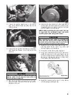
1. Disconnect the wiring harness lead from the ECU.
2. Remove the two lock nuts and screws securing the
ECU to the upper spar.
3. Remove the ECU.
Installing ECU
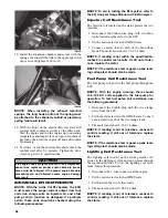
1. Secure the ECU to the upper spar with the screws
and lock nuts.
2. Connect the wiring harness to the ECU.
NOTE: Make sure all connectors are clean and
tight.
Throttle Position Sensor
If the snowmobile is under warranty, the throttle posi-
tion sensor on the EFI system is not a serviceable part.
If the sensor should malfunction, the complete throttle
body assembly must be replaced.
NOTE: If the snowmobile is in warranty, breaking
the seal on the idle screw jam nut or the Phillips-
head screws on the TPS will void warranty.
NOTE: A throttle body assembly with the same
symbol marking on the injectors as the ones being
replaced must be ordered. The symbol is located
on the side of the injector top.
Testing Throttle Position Sensor
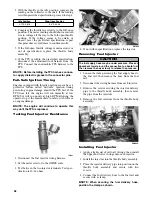
When checking ignition timing, the timing light must
be connected to the number 1 spark plug wire (MAG-
side cylinder). If the number 2 cylinder spark plug
wire is used, the timing light may show a 2° error in
ignition timing when ignition timing is actually cor-
rect.
For example, the correct ignition timing is 12° ± 2°
BTDC at 2000 RPM.
To quickly check TPS operation, measure the timing
according to the chart; then disconnect the TPS wiring
and recheck the timing. A system with a functioning
TPS will show a change in the timing. This is known
as “Fail-Safe Ignition Timing” and is built into the sys-
tem to protect the engine should the TPS fail. If this
change is not seen, the TPS may have failed and must
be checked.
If the ignition timing isn’t 12° ± 2° at 2000 RPM, the
TPS should be checked for proper adjustment using
the Throttle Position Sensor Adjustment Tool Kit and
a digital voltmeter.
Verifying TPS Adjustment Tool
Before using the TPS adjustment tool, verify its bat-
tery condition. The battery used in the tool is a 9-volt
battery. To check battery condition, use a digital volt/
ohmmeter set on DC volt scale. Test between the
adjustment tool black and red jacks. Insert the red lead
of the digital voltmeter into the red jack of the adjust-
ment tool and the black lead of the digital voltmeter
into the black jack of the adjustment tool. The green
power light of the analyzer should now be illuminated.
If voltage is found below 4.9 volts, replace the battery.
NOTE: The battery used in the tool is a 9-volt bat-
tery; also, the Test Harness must be plugged into
the analyzer for testing voltage.
Checking TPS
NOTE: Before using the TPS adjustment tool,
verify its battery condition.
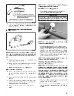
1. Using Throttle Position Sensor (TPS) Adjustment
Tool Kit, connect its wiring harness to the TPS.
Connect the red and black digital voltmeter leads
to the white and black jacks of the TPS adjustment
tool.
2. Ensure that the throttle cable/control rod has the
proper amount of free-play.
Memory Problem Diagnosis Test
Содержание 500 Sno Pro
Страница 1: ...TM SHARE OUR PASSION Operator s Performance Manual Performance Manual 500 Sno Pro...
Страница 2: ......
Страница 6: ...NOTES...
Страница 22: ...16 NOTES...
Страница 68: ...62 NOTES...
Страница 92: ...86 NOTES...
Страница 93: ...87 NOTES...
Страница 94: ...88 NOTES...
Страница 95: ...Printed in U S A Trademarks of Arctic Cat Inc Thief River Falls MN 56701 p n 2258 721...


