59
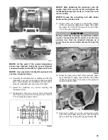
Removing Oil-injection Pump
NOTE: To service the oil-injection pump, the
exhaust system and the air silencer must be
removed.
1. Remove the throttle bodies and secure them out of
the way in an upright position.
2. Disconnect the oil-supply hose from the pump and
plug to prevent oil drainage.
3. Remove the oil-delivery hoses from the intake
flanges.
4. Disconnect the oil-injection cable.
5. Remove the two screws securing the oil-injection
pump and retainer to the crankcase.
6. Pull the oil-injection pump away from the retainer/
crankcase and account for a gasket/O-ring.
NOTE: Remove the oil-injection pump from the
crankcase only if the O-ring or gasket need to be
replaced.
7. Turn the pump sideways; then remove the lower
union bolt. Account for two washer gaskets.
Remove the pump.
8. Remove the remaining union bolts securing the
check valves to the pump. Account for the washer
gaskets.
9. Remove the check valves. Account for two gaskets.
Installing Oil-injection Pump
1. In turn on each front union bolt, install a washer
gasket, check valve, and washer gasket; then
install on the oil-injection pump.
2. Place the gasket and oil-injection pump near the
engine; then install the lower union bolt through a
gasket, check valve, and gasket.
3. Position the oil-injection pump on the engine mak-
ing sure the oil-injection pump gear is correctly
aligned with the oil-injection pump drive gear.
4. Secure the pump with two screws (coated with
blue Loctite #243). Tighten screws to 96 in.-lb.
5. Connect the oil-delivery hoses to the intake
flanges. Secure with clamps.
6. Connect the oil-injection cable to the pump and
secure.
7. Connect the oil-supply hose to the oil-injection
pump inlet fitting. Secure with the clamp.
8. Bleed the oil-injection system.
9. Check the oil-injection system synchronization
(see Synchronizing Oil-Injection Pump). Tighten
the jam nuts securely.
NOTE: Install the exhaust system and the air
silencer.
10. Install the throttle bodies.
Inspecting/Adjusting/
Synchronizing Oil-injection Pump
S
742-331A
1. With the engine off, disconnect the throttle cable
from the throttle lever.
2. Pull the throttle cable to the FULL-OPEN posi-
tion; then using a suitable clamping device, secure
the cable in this position.
3. Check to be sure the mark on the control arm is
aligned with alignment mark on the oil pump boss.
4. If the marks are not aligned, adjust synchroniza-
tion by loosening the jam nut(s) on the adjuster.
Rotate the jam nuts/adjuster nut until proper align-
ment is attained. Tighten jam nut(s).
5. Return the throttle cable to the CLOSED position.
NOTE: Connect the throttle cable to the throttle
lever; then adjust the cable adjusting nut so the
throttle lever moves approximately 1/8 in. before
the oil-injection pump control arm begins to move.
This ensures the throttle/ignition monitor switch
will function properly and will prevent ignition
“cut-out” and spark plug fouling at low RPM oper-
ation.
CAUTION
Care must be taken when securing the cable not to
kink or damage the cable.
CAUTION
Assure that the throttle cable has returned to the fully
closed (idle) position and has not remained in a partial
open position and moves freely from the open posi-
tion to the closed position.
Содержание 2014 SNO PRO 500
Страница 1: ...SNO PRO 500 ...
Страница 16: ...12 Wiring Diagram Hood Harness p n 1686 587 0744 201 ...
Страница 17: ...Wiring Diagram Ignition Main Harness p n 1686 628 0745 605 13 ...
Страница 18: ...14 NOTES ...
Страница 89: ......
Страница 90: ...Printed in U S A Trademarks of Arctic Cat Inc Thief River Falls MN 56701 p n 2259 778 ...


