background image

40

CM160

Crankshaft

NOTE: If any servicing of the connecting rods,

center bearings, or oil-injection pump drive gear is
necessary, Arctic Cat recommends that the crank-
shaft be taken to a qualified machine shop for that
service.

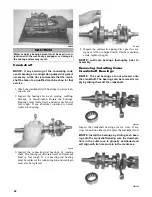
1. Wash the crankshaft with bearings in parts-clean-

ing solvent.

2. Inspect the bearings for wear, scoring, scuffing,

damage, or discoloration. Rotate the bearings.
Bearings must rotate freely and must not bind or
feel rough. If any abnormal condition is noted,
replace the bearing.

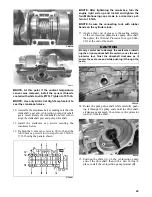
FC039

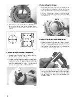
3. Inspect the connecting-rod bearings by rotating

them. The bearings must rotate freely and must not
bind or feel rough. If a connecting-rod bearing
must be replaced, the connecting rod and crank pin
must also be replaced.

FC040

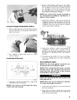
4. Inspect the oil-injection pump drive gear for any

signs of worn or chipped teeth. If either condition
exists, replace the gear.

NOTE: Lubricate bearings thoroughly prior to

assembly.

Removing/installing Outer 

Crankshaft Bearings

NOTE: The end bearings are not pressed onto

the crankshaft. The bearings can be removed sim-
ply by sliding them off the crankshaft.

CM161

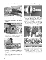
Inspect the crankshaft bearing area for wear. If any
wear is noted on either end, replace the crankshaft end.

NOTE: Install the bearings by sliding each bear-

ing onto the crankshaft making sure the dowel-pin
hole in the outer race is properly positioned and
will align with its hole and pin in the crankcase.

CM161

CAUTION

Water or parts-cleaning solvent must be used in con-
junction with the wet-or-dry sandpaper or damage to
the sealing surface may result.

Содержание 2014 SNO PRO 500

Страница 1: ...SNO PRO 500 ...

Страница 2: ...l snow conditions without proper lubrication or additional idler wheels and the following parts Fuel Filter Light Bulbs Windshield Drive Belt Torn or Punctured Upholstery Wear Bars Brake Pads Spark Plugs Drive Clutch Driven Clutch Wear Parts Wear Strips Shock Absorber s Standard Shock Absorber s Rebuildable Limited to one 1 year or 1000 miles of normal riding conditions replace for defective or le...

Страница 3: ...eason storage instructions If major repair or service is ever required contact an authorized Arctic Cat Snowmobile dealer for professional ser vice At the time of publication all information and illustrations were technically correct Some illustrations used in this manual are used for clarity purposes only and are not designed to depict actual conditions Because Arctic Cat Inc constantly refines a...

Страница 4: ...___________________ Your Arctic Cat Dealer ______________________ Address ___________________________________ Phone ____________________________________ WARNING This snowmobile is a very high performance snowmo bile Because it does accelerate rapidly and is capable of very high speeds it should not be operated by a novice or an inexperienced operator Never accelerate rapidly or drive at high speed...

Страница 5: ... Tension 16 Brake System 17 Drive Belt 17 Handlebar Alignment 17 Handlebar Height Adjustment 18 Steering Speed Ratio Adjustment 18 Recommended Gasoline 18 Preoperation Checks 19 Checking Headlight Aim 19 Track Tension Track Alignment 19 Ski Alignment 20 Test Ride 22 General Information 22 27 Control Locations 22 Engine Break In 22 Speedometer Tachometer 22 Diagnostic Codes 23 Handlebar Tilt 23 Rea...

Страница 6: ...n Width Overall 121 9 cm 48 in Spindle Center to Center Distance Stance 108 0 cm 42 5 in Dry Weight approx 204 1 kg 450 lb Gas Tank Capacity 38 2 l 10 1 U S gal Oil Tank Capacity 2 6 l 2 75 U S qt Chain Case Lubricant Capacity 236 ml 8 fl oz Gasoline Recommended 87 Octane Pre Mix Oil 32 1 Ratio Arctic Cat Formula 50 Injection Oil Chain Case Lubricant Synthetic Chain Lube Suspension Grease All Temp...

Страница 7: ... 50 68 75 102 100 136 Description Resistance Test Test Value Test Connections Ignition Coil Primary Secondary 0 24 0 36 ohm 6800 10 200 ohms orange black high tension wire orange red high tension wire Charge Coil 1 8 8 13 2 ohms black red green red Charge Coil 2 8 8 13 2 ohms brown white green red Lighting Coil 0 08 0 12 ohm yellow yellow Ignition Timing Sensor 80 8 121 ohms green white brown gree...

Страница 8: ...40 C 104 F 0 955 1105 42 C 44 F 4 553 55100 38 C 100 F 1 023 1214 44 C 47 F 4 591 63200 36 C 97 F 1 091 1323 46 C 51 F 4 629 71300 34 C 93 F 1 159 1432 48 C 54 F 4 667 79400 32 C 90 F 1 227 1541 50 C 58 F 4 705 87500 30 C 86 F 1 295 1650 Temperature Volts Ohms Temperature Volts Ohms 100 C 212 F 0 113 555 28 C 82 F 1 230 8540 98 C 208 F 0 121 595 26 C 79 F 1 322 9530 96 C 205 F 0 128 635 24 C 75 F ...

Страница 9: ...nly Drive Clutch Spring Chart Titanium Engine type Squish Gap 500 cc 0 059 in Bore x Stroke A 0 15 0 006 B 0 15 0 006 C 0 4 0 015 G Runout Points D and F 002 71 mm x 63 mm 2 795 x 2 480 114 6 mm 4 515 66 5 mm 2 618 113 4 mm 4 465 26 9 mm 1 062 D 5 mm 0 196 F 5 mm 0 196 Drive Clutch Cam Arm Torque Bracket p n Spring Color p n Grams Degrees 0746 435 0646 229 Yellow White 0746 826 64 0 40 38 Driven C...

Страница 10: ...46 668 55 0 0746 742 83 5 0746 669 60 0 0746 744 50 0 0746 670 65 0 0746 748 46 0 0746 671 70 0 0746 749 65 0 0746 672 75 0 0746 771 44 0 0746 673 80 0 0746 772 42 0 0746 676 70 0 0746 773 85 0 0746 678 55 0 0746 786 63 0 0746 687 57 0 0746 787 44 0 0746 689 69 0 0746 788 47 5 0746 690 47 0 0746 789 42 0 0746 691 44 0 0746 791 60 0 0746 692 50 0 0746 792 47 0 0746 694 63 0 0746 793 63 0 0746 695 6...

Страница 11: ...9 Tooth 2 52 Pitch Sprockets Ratio Chain Pitch 6000 7000 8000 9000 10 000 20 46 0 435 74 62 3 72 6 83 0 93 4 103 8 20 45 0 444 74 63 6 74 1 84 7 95 3 105 9 21 45 0 467 74 66 8 78 0 89 1 100 3 111 4 19 40 0 475 70 68 0 79 3 90 7 102 0 113 3 21 41 0 512 72 73 3 85 5 97 7 109 9 122 1 20 39 0 513 70 73 4 85 7 97 9 110 1 122 4 22 41 0 536 72 76 7 89 5 102 3 115 1 127 9 22 40 0 550 72 78 7 91 8 105 0 11...

Страница 12: ...1602 417 43 15 1602 418 44 15 1602 481 45 16 2602 223 45 15 1602 482 46 16 2602 074 46 16 2602 224 WIDE SPROCKET w 15 Link Chain 19 15 1602 548 20 15 1602 600 21 15 1602 685 23 15 2602 109 39 16 1602 686 42 16 1602 687 43 16 1602 549 44 16 1602 688 45 16 1602 689 46 16 1602 690 WIDE SPROCKET w 17 Link Chain 19 15 1602 796 20 15 1602 735 21 15 1602 797 43 16 1602 734 44 16 1602 802 45 16 1602 803 4...

Страница 13: ... 50 2703 386 13 00 in 160 8 00 10 00 2703 387 13 00 in 190 8 50 10 50 2703 406 13 00 in 145 8 24 10 24 P N Tool 0744 020 Inflation Needle 0644 486 Gas Shock Retaining Blocks 0644 544 Replacement Needle 0644 169 Piston Location Tool 0644 151 Nitrogen Regulator 0644 268 Bearing Cap Seal Protector 0644 403 Bearing Cap Seal Protector 1 2 in O D x 3 8 in I D 0644 404 Bearing Cap Seal Protector 5 8 in O...

Страница 14: ...5 in Piston Depth 2 26 in 1 125 x 0 093 in Top out washer Part Number Description Compression Piston Side Rebound Piston Side 2704 039 Front Arm Shock 1 300 x 0 010 in 1 100 x 0 008 in Extended Length 12 34 in Rebuild Kit p n 2604 815 1 300 x 0 010 in 0 600 x 0 004 in Collapsed Length 8 55 in 1 300 x 0 010 in 0 700 x 0 004 in Stroke 3 79 in 1 300 x 0 008 in 0 900 x 0 004 in 1 300 x 0 008 in 1 125 ...

Страница 15: ...603 350 Valve 1 300 OD X 0 377 ID X 0 010 TH 0603 891 Valve 1 300 OD X 0 377 ID X 0 012 TH 0603 890 Valve 1 300 OD X 0 377 ID X 0 015 TH 2603 902 Valve 0 550 OD X 0 377 ID X 0 020 TH AC PN Description 2604 647 Valve 1 425 OD X 0 377 ID X 0 010 TH 2604 632 Valve 1 425 OD X 0 377 ID X 0 012 TH 2604 633 Valve 1 425 OD X 0 377 ID X 0 015 TH 3604 577 Valve 1 600 OD X 0 377 ID X 0 008 TH 2604 631 Valve ...

Страница 16: ...12 Wiring Diagram Hood Harness p n 1686 587 0744 201 ...

Страница 17: ...Wiring Diagram Ignition Main Harness p n 1686 628 0745 605 13 ...

Страница 18: ...14 NOTES ...

Страница 19: ...nstall the windshield O rings B 4 With the windshield in place install the expansion nuts C into the hood then install the machine screws D and the snap caps E INSTALLING SPINDLE A ARM 743 066B 1 Install the A arms onto the spindle and secure with washers and lock nuts Tighten lock nuts to 45 ft lb 2 Install the steering tie rod to the spindle as shown in illustration Install the lock nut and tigh...

Страница 20: ...ng loca tion of the chassis 2 Secure the bar with the two mounting brackets four cap screws and four washers 3 Tighten cap screws evenly to 96 in lb NOTE The washers must be positioned between the chassis and the mounting brackets 4 Position the sway bar link onto the lower A arm and the sway bar Install the cap screws and lock nuts Tighten the lock nuts to 20 ft lb OIL INJECTION PUMP SYNCHRONIZAT...

Страница 21: ... belt is sitting at the top of the driven clutch sheaves 3 Place a straightedge on the top of the drive belt The straightedge should reach from the drive clutch to the top of the driven clutch 4 Using a stiff ruler centered between the drive clutch and driven clutch push down on the drive belt just enough to remove all slack and note the amount of deflection The deflection should be approximately ...

Страница 22: ... too loose STEERING SPEED RATIO ADJUSTMENT NOTE The lower steering post bearing housing is not symmetrical therefore rotating it 180 moves the steering post closer to or farther away from the drag link which changes the steering ratio The lower speed ratio standard position is when the steering post is adjusted closest to the drag link 1 Remove the hood side access panels and the air silencer asse...

Страница 23: ...a horizontal mark on the aiming surface 4 Make a vertical mark which intersects the horizon tal mark on the aiming surface directly in front of the headlight 5 Engage the brake lever lock and start the engine Move the headlight dimmer switch to the HIGH beam position DO NOT USE LOW BEAM 6 Observe the headlight beam aim Proper aim is when the most intense beam is centered on the ver tical mark 5 cm...

Страница 24: ...ive lugs closer to the rear idler wheel rotate the adjusting bolt clockwise 1 1 1 2 turns 10 Check track alignment and make necessary adjust ments until proper alignment is obtained NOTE Make sure correct track tension is main tained after adjusting track alignment 11 Loosen the right side rear axle nut just enough to apply blue Loctite 243 to the axle threads then tighten the nut to 40 45 ft lb S...

Страница 25: ...pindle Record the mea surements taken for the right side 8 If ski alignment is not as specified adjust the align ment of the ski s not parallel to the straightedge Adjusting NOTE The following procedure can be used to adjust the alignment of either ski 1 Unlock the steering tie rod by loosening the jam nuts A NOTE The inside jam nuts are left hand thread Care should be taken to rotate them in the ...

Страница 26: ... of the pads 2 Allow the engine to cool then visually check cool ant level Add coolant as necessary 3 Recheck track alignment and tension 4 Check the engine compartment and underneath the snowmobile for any signs of fluid leaks gas coolant General Information CONTROL LOCATIONS 0744 861 ENGINE BREAK IN The engine when new or rebuilt requires a short break in period before the engine is subjected to...

Страница 27: ...w one aligning the holes with the holes in the brack ets then rivet the rear bumper to both sides of the tunnel EXHAUST SYSTEM The exhaust system is designed to reduce noise and to improve the total performance of the engine If any exhaust system component is removed from the engine and the engine is run severe engine damage will result AIR INTAKE SILENCER Used in conjunction with the throttle bod...

Страница 28: ...ng the snowmobile at high altitudes it may be necessary to change certain component parts of the drive clutch If the operator does not feel quali fied to change clutch components see an authorized Arctic Cat Snowmobile dealer for this service DRIVE CLUTCH DRIVEN CLUTCH ALIGNMENT The parallelism and the offset between the drive clutch and driven clutch are set at the factory Normally no adjustment ...

Страница 29: ...roved fuel efficiency with maximum mileage in every condition 5 Engine RPM more stable in every condition Precautions 729 325A Flooded Engine If the engine should become flooded set the brake lever lock compress the throttle lever to the full open position and crank the engine over until it starts and clears itself Release the brake lever lock Fuel System The fuel is first drawn into the electric ...

Страница 30: ...tly Once the engine coolant temperature reaches the specified temper ature 93 C 200 F the temperature sensor will signal the ECM to go into the rich mode to protect the engine from overheating At this time the check engine light will stay on Throttle Position Sensor This sensor located at the end of the throttle shaft is a potentiometer essentially a resistor This sensor transforms the throttle va...

Страница 31: ...ational Snowmobile Racing Inc regulations as they pertain to the type of racing you participate in Arctic Cat has a variety of studding products available from your authorized Arctic Cat Snowmobile dealer TOWING If this snowmobile is to be towed by another snowmo bile do not tow using the loops in the skis The tow rope should be attached to the spindles Operating Instructions STARTING AND STOPPING...

Страница 32: ...emperature and the temperature of the brake fluid If loss of brakes has occurred because of high fluid temperatures do not operate the snowmobile until the cool down period has expired and brake lever firmness has returned 2 Be sure to maintain the brake fluid at the proper level and take care not to get any moisture in the system as moisture in the brake fluid lowers the boiling point If the brak...

Страница 33: ...d mark the lubricant level is satisfactory If the lubricant level is at or below the add mark proceed to step 4 4 If oil is low add synthetic chain lube through the oil level stick filler hole When the oil level is correct install the oil level stick NOTE If excessive oil deposits are noticed the chain case must be serviced Also when the oil level is at the add mark approximately 60 ml 2 fl oz of ...

Страница 34: ...e on its side A piece of card board should be used to protect the finish on the hood and belly pan NOTE Prior to tipping the snowmobile on its side apply the brake and set the brake lever lock 3 Remove ice and snow buildup from the skid frame to expose the grease fittings 0741 175 0744 072 4 Lubricate the grease fittings with an all tempera ture grease ...

Страница 35: ...nd retighten sprocket cap screws Brake Fluid I R I Replace brake hose every year Brake Pads I I I Inspect for wear Throttle Cable Lever I I I Inspect for proper adjustment and wear Fuel Hoses I I I Inspect for wear and pinching Replace yearly Exhaust System I I I Check for cracks and missing springs Pistons Rings R Reed Valves I Replace yearly Front Suspension I I I Apply grease to bellcrank fitti...

Страница 36: ...n chamber to the upper spar then remove the springs and hairpin clip securing the expansion chamber and resonator to the chassis and remove the chamber and resonator IO032A IO033A 2 Remove the six cap screws securing the recoil to the engine and note the location of the ground wire for assembling purposes PRE RACE PRACTICE CHECKLIST WHAT TO CHECK CHECK FOR Spark Plugs 1 Tightness and loose end cap...

Страница 37: ...e harness connectors IO035A NOTE For installing purposes note the loca tions of the cable ties securing the harnesses 7 Remove the four lock nuts and cap screws securing the oil tank to the chassis then disconnect the low oil sensor from the back side of the tank Remove the oil hose from the oil pump and discard the clamp Plug the oil line and remove the oil tank IO037A IO039A 8 Loosen the clamp a...

Страница 38: ...en the jam nuts of the oil injection cable Remove the cable from the oil pump and account for the nylon washer IO046A 12 Remove the exhaust manifold from the engine Account for the flange nuts and gaskets 13 Remove the two PTO side cap screws A secur ing the engine to the chassis 0744 860 14 Remove the cap screw B securing the upper MAG side engine mount to the chassis then remove the lower cap sc...

Страница 39: ...ler p n 0744 040 or suitable substitute remove the flywheel from the crank shaft by tightening the puller bolt striking the head of the puller bolt with a hammer and tighten ing again Repeat this procedure until the flywheel is free Account for the key CM013 NOTE To ensure the cleanliness of the flywheel magnets place the flywheel with the magnets fac ing upward on a clean bench 4 Remove the two s...

Страница 40: ...e the PTO side piston pin circlip from the PTO side piston then remove the MAG side pis ton pin circlip from the MAG side piston CM149 9 Using Piston Pin Puller p n 0644 328 remove the piston pins from both pistons NOTE For proper assembly keep all MAG side components and all PTO side components sepa rated Assemble them on their proper sides FC029 10 Lift the pistons clear of the connecting rods a...

Страница 41: ... installing two crankcase cap screws in opposite corners leaving the heads approximately 6 mm 1 4 in out Using a plastic hammer and lifting on the ends of the crankshaft tap on each cap screw head until the case halves separate Remove the cap screws FC034 19 Lift the bottom half of the crankcase off the top half and account for the crankcase dowel pins 20 Lift the crankshaft free from the top half...

Страница 42: ... or damage the combustion chambers or the sealing surfaces 2 Inspect the spark plug holes for any damaged threads 3 Inspect the cylinder head for flatness using a straightedge and a feeler gauge Acceptable warp age must not exceed 0 002 in NOTE If the warpage exceeds specification resurface the cylinder head using procedures identified in step 4 FS270 4 Place the cylinder heads on a Surface Plate ...

Страница 43: ...If scuffing or seizure marks are too deep to correct with the sandpaper it will be necessary to replace the piston 5 Inspect the perimeter of each piston for signs of excessive blowby Excessive blowby indicates worn piston rings or an out of round cylinder NOTE If synthetic oil is being used a certain amount of blowby may be visible under normal use Crankcase 1 Wash the crankcase halves in parts c...

Страница 44: ...connecting rod and crank pin must also be replaced FC040 4 Inspect the oil injection pump drive gear for any signs of worn or chipped teeth If either condition exists replace the gear NOTE Lubricate bearings thoroughly prior to assembly Removing installing Outer Crankshaft Bearings NOTE The end bearings are not pressed onto the crankshaft The bearings can be removed sim ply by sliding them off the...

Страница 45: ...g hole and push them up against the inner cylinder bore towards the MAG side and PTO side of the cylinder 3 Pull the recoil rope and crank the engine over sev eral times while the solder is being held firmly in place 4 Remove both pieces of solder from the cylinder Using the micrometer measure the very end of the squeezed solder piece Record the reading NOTE If the solder hasn t been squeezed by t...

Страница 46: ...ap 1 Place each piston ring in the wear portion above the exhaust port of its respective cylinder Use the pis ton to position each ring squarely in each cylinder 2 Using a feeler gauge measure each piston ring end gap Acceptable ring end gap must be within 0 008 0 016 in FC045 Piston Pin And Piston pin Bore 1 Measure the piston pin diameter at each end and in the center Acceptable piston pin measu...

Страница 47: ...he crankshaft end Zero the indicator and rotate the crankshaft slowly Note the amount of crankshaft runout total indicator reading FC046 4 Position the indicator contact point against the crankshaft at location point C center Zero the indicator and rotate the crankshaft slowly Note the amount of crankshaft runout total indicator reading 5 If runout exceeds 0 002 in at any of the check points the c...

Страница 48: ... oil seals with grease then slide the seals onto the crank shaft making sure the spring side of each seal faces the center of the crankshaft 8 Apply oil to the crankshaft bearings then install the crankshaft into the upper crankcase half Be sure the alignment hole in each bearing is posi tioned over its respective retaining pin in the crankcase then seat the crankshaft CM045A NOTE To check the bea...

Страница 49: ... up and install and tighten the four MAG housing cap screws in a crisscross pat tern to 18 ft lb NOTE Secure the connecting rods with rubber bands on the cylinder studs 13 Apply a thin coat of grease to the sealing surface of the oil injection pump water pump driveshaft then place the Oil Seal Protector Tool p n 0644 219 at the end of the shaft FS233A 14 Rotate the pump driveshaft while carefully ...

Страница 50: ...side of the washer is lubricated with a light coat of grease and directed toward the impeller Apply blue Loc tite 243 to the threads of the cap screw and tighten to 108 in lb NOTE For assembling purposes lubricate the rubber side of the washer before installing 20 Apply high temperature sealant to the crankcase water pump cover seam then install the dowel pins into the crankcase FC133A NOTE Do not...

Страница 51: ...ermostat cap with thermostat Secure the cap with cap screws and tighten in a crisscross pattern to 96 in lb CM157A 23 With new gaskets in place install the reed valve assemblies and intake flanges Secure in a criss cross pattern to 96 in lb then install the oil injec tion hoses to the flanges and oil injection pump Secure with the clamps 24 With new washer gaskets place the check valve assembly in...

Страница 52: ... either side of the ring keeper then apply oil to the piston assemblies and cylinder bores Remove the rubber bands or hoses from the connecting rods 30 Install the dowel pins into the crankcase then place the cylinder base gasket into position on the crankcase 31 In turn on each cylinder place a piston holder or suitable substitute beneath the piston skirt and square the piston in respect to the c...

Страница 53: ... rings Start and finger tighten the remaining cap screws being very careful not to move the cylinder head 36 From step 35 in two steps tighten the 6 mm cap screws to 96 in lb and the 8 mm cap screws to 19 ft lb using the pattern shown Tighten the spark plugs to 19 ft lb 0738 204 NOTE After tightening the 8 mm cap screws tighten the two remaining 6 mm cap screws to 96 in lb NOTE At this point press...

Страница 54: ...the spacer A and related cap screws prop erly oriented install the lower MAG side and PTO side engine brackets to the crankcase then install the left side mounting bracket to the mag neto housing and tighten all cap screws coated with blue Loctite 243 to 40 ft lb 744 859A 2 Place the engine into the chassis from the MAG side then position the engine to the mounting locations in the chassis In orde...

Страница 55: ... oil injection hose from the oil tank to the oil pump IO047A IO039A 9 Connect the coolant hose A to the throttle body assembly then connect the gasline supply hose B to the delivery pipe of the throttle body assem bly Secure with the clamps 745 867A 10 With the harness routed properly connect the two injector harness connectors C and the throttle position sensor connector D to the throttle body as...

Страница 56: ...ead then roll the belt back and forth while closing the sheaves allowing the sheaves to fully close Verify proper drive belt deflection 743 067B 17 Apply a thin coat of high temperature silicone sealant to each exhaust port then install the exhaust gaskets 18 Apply a thin coat of high temperature silicone sealant to the mating surfaces of the exhaust mani fold then install the exhaust manifold and...

Страница 57: ... the double plug with the two orange wires from the ECM 2 Set the meter selector to the OHMS scale Connect a meter lead to each of the two orange leads 3 The meter must show 1 52 2 28 ohms NOTE If reading is out of tolerance recheck to confirm reading If still out of tolerance replace the stator NOTE If the resistance test is good a peak read ing voltage test should also be made Lighting Coil Resi...

Страница 58: ...S adjustment tool verify its battery condition 1 Using Throttle Position Sensor TPS Adjustment Tool Kit p n 3639 891 connect its wiring har ness to the TPS Connect the red and black digital voltmeter leads to the white and black jacks of the TPS adjustment tool 2 Ensure that the throttle cable control rod has the proper amount of free play 3 With the throttle in the idle position compare the readi...

Страница 59: ...ng harness to the injectors making sure the number 1 harness is connected to the MAG side injector Testing Ignition Timing Sensor Resistance 0729 627 NOTE This sensor is located inside the magneto case next to the flywheel and the recoil starter and the flywheel must be removed to access the sensor 1 Disconnect the sensor connector green white and brown green from the ECM 2 Set the selector in the...

Страница 60: ...resistance reading to the Voltage Resistance Chart Coolant Temperature in this manual If resistance is not within the specifica tion replace the sensor NOTE A coolant temperature sensor voltage test can be made using the EFI Analyzer NOTE The coolant temperature sensor is located at the lower half of the crankcase To remove the sensor the engine must be removed Testing Air Temperature Sensor Resis...

Страница 61: ...ing the throttle It may idle slowly and stop Restart using the same procedure until the engine starts and builds RPM on its own 8 Check the cooling system 9 Adjust the throttle cable and oil pump cable syn chronization as necessary INDIVIDUAL FUEL SYSTEM COMPONENTS Removing Throttle Body Flange NOTE The expansion chamber and air intake silencer must be removed for this procedure 1 Loosen the clamp...

Страница 62: ... on the oil injection pump secure with the jam nuts 6 Install the oil injection cable on the control arm secure with a washer and E clip 7 Secure the throttle cable to the handlebar and steering post with cable ties 8 Install the handlebar pad 9 Adjust the throttle cable tension by turning the jam nuts in the appropriate direction until 0 030 0 060 in free play exists in the throttle lever and the...

Страница 63: ...il delivery hoses to the intake flanges Secure with clamps 6 Connect the oil injection cable to the pump and secure 7 Connect the oil supply hose to the oil injection pump inlet fitting Secure with the clamp 8 Bleed the oil injection system 9 Check the oil injection system synchronization see Synchronizing Oil Injection Pump Tighten the jam nuts securely NOTE Install the exhaust system and the air...

Страница 64: ...ine run the engine at recom mended RPM for 2 minutes Compare the amount of oil used against the specifications chart 9 If the oil injection pump output does not meet the specifications see Testing Oil Injection Check Valves in this section 10 Disconnect the oil usage tool remove the plug from the reservoir attach the oil supply hose to the oil reservoir NOTE After testing the oil pump the oil pump...

Страница 65: ...4 Remove the cap screws securing the slide rail assembly NOTE At this time it is recommended to have the snowmobile tipped on the left side 5 Remove the four screws securing the right side toe shield then remove the six cap screws securing the chain case cover Remove cover 6 Loosen the jam nut and the chain tensioner enough to remove the chain and sprockets then remove the chain and sprockets Remo...

Страница 66: ...it will pro duce an inaccurate reading 2 Measure the distance between the brake lever and the handlebar The distance must be greater than 2 54 cm 1 in 740 159B 3 If the resultant distance is less than specified it must be adjusted BLEEDING BRAKE SYSTEM If the brake lever feels spongy when applied the brake system may need to be bled To bleed the brake use the following procedure 1 Remove the reser...

Страница 67: ...ll one brake pad out of the caliper assembly NOTE Changing one pad at a time will prevent one piston from pushing out the other piston from the caliper 5 Using a flat blade tool slowly and carefully push the piston into the caliper 6 Position the new brake pad into the caliper 7 Repeat steps 4 6 for the other pad then secure the pads with the pin 8 Remove the reservoir cover and remove the remaini...

Страница 68: ...ntil the movable sheave opens far enough to remove the drive belt 743 067B 5 When the sheaves are fully apart pull up on drive belt and roll belt over stationary sheave until it is free of the driven clutch 6 When the belt is free of driven clutch remove the belt from the drive clutch Installing Drive Belt 1 Place the belt so the part number can be read between the sheaves of the drive clutch 2 Wi...

Страница 69: ... or damage NOTE Flat spots or diameter cannot be less than 23 mm 0 925 in 4 Inspect shaft for nicks or burrs 5 Using a spring compression scale measure spring rate at proper load heights secondary springs measured at load heights of 2 2 in and 1 1 in NOTE If a spring rate measures less than 10 of specified load height it must be replaced 6 Measure the inside diameter of the movable sheave bushing ...

Страница 70: ... there is a need to make changes there are several spring and shock sizes to choose from While making these changes keep the following points in mind Heavier Lighter Springs 1 Using heavier or lighter springs will affect the shock function Changes in compression or rebound damping may be necessary to attain desired performance 2 With heavier springs the front end will become more aggressive in the...

Страница 71: ... place it on a clean lint free rag or towel 9 Remove the shock from the vise and pour shock oil from body tube into a proper disposal con tainer DO NOT REUSE OLD SHOCK OIL 10 Using Gas Shock Retaining Blocks p n 0644 486 secure the shock body in the vise taking care not to crush the shock body then using a propane torch heat the body cap to soften the Loctite Using a crescent wrench or cap socket ...

Страница 72: ...f the shaft then apply grease to both the tool and the shaft 2 Slide a new bearing assembly and the aluminum spacer over the bullet tool onto the shaft FS279 3 Install a new piston O ring and step cut piston band 4 Place the preserved shim stack piston assembly onto the shaft then install the piston lock nut and tighten to 22 ft lb FS280 5 Slide the shock body over the piston shaft assem bly 6 Thr...

Страница 73: ... that the valve is directed away from face and body and pressurize the reservoir to 250 psi FS285 20 Using a 3 32 in hex key install the button head screw into the air valve Dispose of used shock oil 21 Lubricate and install the O rings and spacers into the eyelets ADJUSTING REAR TRANSFER ADJUSTER CAMS The transfer system has seven positions To make cam adjustment use the following procedure 741 2...

Страница 74: ... bar is to assist in turning the snowmobile to minimize ski wear and to maintain good steering control If the snowmo bile is operated primarily in deep snow ski wear bar wear will be minimal however if the snowmobile is operated on terrain where the snow cover is minimal the ski wear bar will wear faster To maintain positive steering characteristics Arctic Cat recommends that the ski wear bars be ...

Страница 75: ...wear strips be checked weekly and replaced as necessary Measure the wear strips at 25 4 cm 10 in intervals Wear strips must be 10 7 mm 0 42 in thick or thicker If wear strip mea surements are less than specified replacement of both wear strips is necessary to prevent premature track clip wear and possible track damage NOTE The rail wear strips will wear rapidly if the snowmobile is operated on ter...

Страница 76: ...e idling spray an Engine Storage Preserver into the throttle bodies until the engine exhaust starts to smoke heavily or until the engine starts to drop in RPM Turn engine off 5 Plug the exhaust system outlet with a clean cloth 6 With the tether switch cap removed A Disconnect the high tension leads from the spark plugs then remove the plugs connect them to the leads and ground them on the cylinder...

Страница 77: ... are tight ened to specifications 12 If not done during preparation for storage lubri cate the rear suspension spindles and steering arms with an all temperature grease Genuine Arctic Cat Products Arctic Cat Oil Developed tested and proven espe cially for Arctic Cat Snowmobile engines Arctic Cat Oil is the only oil authorized by Suzuki and Arctic Cat engineers for use in Arctic Cat Snowmobile engi...

Страница 78: ...for reconditioning Arctic Cat snow mobile engine cylinders 0644 291 Flywheel Spanner Wrench p n 0144 007 Usage Hold starter cup while removing installing fly wheel nut 0144 007 Flywheel Puller Insert p n 0644 179 Usage Protect the crankshaft end during flywheel removal 0644 179 Flywheel Puller p n 0744 040 Complete Set p n 0643 086 Body p n 0643 087 Bolt p n 0423 482 6 mm Cap Screw p n 0423 483 8 ...

Страница 79: ... Extractor Nut Only Medium p n 0643 075 Extractor Nut Only Large p n 0643 072 Threaded T Handle Usage Remove piston pins 0644 328 Spring Tool p n 0644 554 Usage Remove install exhaust springs 0644 554 Spring Tool p n 0644 072 Usage Remove install exhaust springs 0644 072 Stud Runner p n 0644 018 6 mm p n 0644 019 8 mm p n 0644 020 10 mm Usage Install studs on cylinders and crankcase 0644 020 Surfa...

Страница 80: ... 093 12 mm Adapter Usage Test cylinder compression on all Arctic Cat engines 0444 213 Engine Timing Gauge p n 0144 009 Usage Static time engines without CDI ignition 0144 009 Timing Light p n 0644 296 Usage Check ignition timing 0644 296 90 Hex Driver 1 4 in p n 0644 550 Usage Make carburetor adjustments on all twin and tri ple cylinder engines Also for any hard to get at hex nuts A 6 mm Hex B 0 1...

Страница 81: ...ch Puller Arctic p n 0744 062 Usage Remove drive clutch from the crankshaft on 2010 2013 models 0644 207 Drive Belt Deflection Tool p n 0644 424 Usage Adjust driven clutch for proper drive belt deflec tion and aid in drive belt removal on Sno Pro 600 model with Team Industries driven clutch 0644 424 Drive Clutch Spanner Wrench p n 0644 136 Usage Hold Comet and Arctic round shaft drive clutch in pl...

Страница 82: ... clutches 0644 449 Track Clip Installation Tool p n 0644 194 Usage Install track clips on Camoplast and Yokohama rubber tracks 0644 194 Track Stud Hole Drill 7 mm p n 1639 629 Usage Drill 7 mm hole through rubber tracks for install ing studs 1639 629 Throttle Position Sensor TPS Adjustment Tool Kit p n 3639 891 Complete Set p n 1686 436 Harness Only p n 0644 359 Torx Head Screwdriver 25 Only p n 0...

Страница 83: ...nstall skid frame idler wheels 0644 570 Floating Piston Location Gauge p n 0644 350 Usage Precisely locate and measure floating piston depth without use of a calipers 0644 350 Gas Shock Retaining Blocks Zero Pro p n 0644 486 Usage Hold shock secure during disassembly and assembly 0644 334 Gas Shock Shaft Clamping Tool p n 0644 543 Usage Hold shock secure during disassembly and assembly on 2008 Sno...

Страница 84: ...hock absorbers 0644 539 Nitrogen Regulator p n 0644 151 Usage Recharge rebuildable gas shock absorbers 0644 151 Piston Location Tool p n 0644 169 Usage Precisely locate the floating piston in the rebuild able gas shock absorber 0644 169 Piston Location IFP Tool p n 0644 575 Usage Precisely locate the floating piston IFP in the rebuildable gas shock absorber 0644 575 Axle Nut Spanner Wrench p n 064...

Страница 85: ...isconnect Coupler p n 0644 308 remove and install bolts and screws 0644 316 Insert Holder 5 16 in p n 0644 315 Usage With Torx Bit Insert p n 0644 314 remove and install torx head screws 0644 315 Phillips Head Bits 1 4 in Hex Drive p n 0644 319 2 p n 0644 318 3 Usage With Quick Disconnect Coupler p n 0644 308 remove and install Phillips head screws 0644 318 Quick Disconnect Coupler p n 0644 308 Us...

Страница 86: ...ll rivnuts 0644 232 Toggle Switch Wrench p n 0644 566 Usage Remove install a toggle switch on 2010 2013 Sno Pro 500 0644 566 Rivnut Tool Insert Bit p n 0644 233 1 4 x 20 p n 0644 405 10 32 p n 0644 430 5 16 x 18 p n 0644 431 3 8 x 16 Usage With Rivnut Tool p n 0644 232 and Replace ment Rivnuts replace rivnuts 0644 233 Vacuum Test Pump p n 0644 131 Usage Check components for air leaks 0644 131 EFI ...

Страница 87: ... Usage Remove and install nuts and bolts 0644 257 T Wrench p n 0644 021 Usage Drive 3 8 in square drive sockets 0644 021 Torx Bit Insert 5 16 in Hex Drive p n 0644 314 Usage With Insert Holder p n 0644 315 remove and install torx head screws 0644 314 Torx Bits 1 4 in Hex Drive p n 0644 312 25 p n 0644 393 27 p n 0644 215 30 p n 0644 313 40 Usage With Quick Disconnect Coupler p n 0644 308 remove an...

Страница 88: ...bile Division Application of council directives Issued by European Commission EMC Directive 2004 108 EC EC Machinery Directive 2006 42 EC Type of Equipment Snowmobile Brand Name Arctic Cat Model Numbers S2014ACCPRUSG Standards to which conformity is declared EMC MACHINERY EN 55012 EN 61000 6 2 EN 12100 2010 Manufacturer if not issuing agent Arctic Cat Inc 601 Brooks Ave S Thief River Falls MN 5670...

Страница 89: ......

Страница 90: ...Printed in U S A Trademarks of Arctic Cat Inc Thief River Falls MN 56701 p n 2259 778 ...

Отзывы: