39
Cylinders
1. Using a non-metallic carbon removal tool, remove
carbon buildup from the exhaust ports.
2. Wash the cylinders in parts-cleaning solvent.
3. Inspect the cylinders for pitting, scoring, scuffing,
and corrosion. If marks are found, repair the sur-
face with a Ball Hone (p/n 0644-292) and honing
oil.
NOTE: To produce the proper 45° crosshatch pat-
tern, maintain a low drill RPM. If honing oil is not
available, use a lightweight, petroleum-based oil.
Thoroughly clean the cylinders after honing using
detergent soap and hot water and dry with com-
pressed air; then immediately apply oil to the cyl-
inder bores. If a bore is severely damaged or
gouged, the cylinder must be replaced.
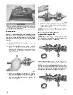
4. Place the head surface of each cylinder on the sur-
face plate covered with #400 grit wet-or-dry sand-
paper. Using light pressure, move each cylinder in
a figure eight motion. Inspect the surface for any
indication of high spots. A high spot can be noted
by a bright metallic finish. Correct any high spots
before assembly by continuing to move the cylin-
der in a figure eight motion until a uniform bright
metallic finish is attained.
Piston Assembly
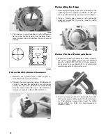
1. Using a non-metallic carbon removal tool, remove
the carbon buildup from the dome of each piston.
2. Snap an old piston ring into two pieces; then grind
the end of the old ring to a 45° angle and to a sharp
edge. Using the sharpened ring as a tool, clean car-
bon from the ring-grooves. Be sure to position the
ring with its tapered side up.
3. Inspect each piston for cracks in the piston pin and
skirt areas.
4. Inspect each piston for seizure marks or scuffing.
Repair with #400 grit wet-or-dry sandpaper and
water or honing oil.
AN135
NOTE: If scuffing or seizure marks are too deep
to correct with the sandpaper, it will be necessary
to replace the piston.
5. Inspect the perimeter of each piston for signs of
excessive “blowby.” Excessive “blowby” indicates
worn piston rings or an out-of-round cylinder.
NOTE: If synthetic oil is being used, a certain
amount of “blowby” may be visible under normal
use.
Crankcase
1. Wash the crankcase halves in parts-cleaning sol-
vent.
NOTE: Before washing the crankcase halves,
make sure the four bearing dowel pins have been
removed and accounted for.
2. Inspect the crankcase halves for scoring, pitting,
scuffing, or any imperfections in the casting.
3. Inspect all threaded areas for damaged or stripped
threads.
4. Inspect the bearing areas for cracks or excessive
bearing movement. If evidence of excessive bear-
ing movement is noted, the crankcase must be
replaced.
5. Inspect the bearing dowel pins for wear.
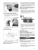
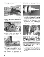
6. Inspect the sealing surfaces of the crankcase
halves for trueness by placing each crankcase half
on the surface plate covered with #400 grit wet-or-
dry sandpaper. Using light pressure, move each
half in a figure eight motion. Inspect the sealing
surfaces for any indication of high spots. A high
spot can be noted by a bright metallic finish. Cor-
rect any high spots by continuing to move the half
in a figure eight motion until a uniform bright
metallic finish is attained.
NOTE: Care must be taken not to remove an
excessive amount of aluminum, or the crankcase
must be replaced. If excessive aluminum is
removed, too much pre-load will be exerted on the
crankshaft bearings when assembled.
CAUTION
Water or parts-cleaning solvent must be used in con-
junction with the wet-or-dry sandpaper or damage to
the sealing surface may result.
CAUTION
Improper cleaning of the ring-grooves by the use of
the wrong type of ring-groove cleaner will result in
severe damage to the piston.
Содержание 2014 SNO PRO 500
Страница 1: ...SNO PRO 500 ...
Страница 16: ...12 Wiring Diagram Hood Harness p n 1686 587 0744 201 ...
Страница 17: ...Wiring Diagram Ignition Main Harness p n 1686 628 0745 605 13 ...
Страница 18: ...14 NOTES ...
Страница 89: ......
Страница 90: ...Printed in U S A Trademarks of Arctic Cat Inc Thief River Falls MN 56701 p n 2259 778 ...


